Rockwell Automation 2706 DL20 SERIES G USER MANUAL User Manual
Page 77
Chapter 7
The Parallel Port
7–5
Parallel Port Strobe Lines
If the DL20 receives a value like 145, this could mean either a variable 145
or a message number 145. The function
of the strobe lines (MS0 and MS1)
is to tell the DL20 what to do with information on the data lines (D0-D9).
When strobing over a variable, the high order data should be strobed over
first. The variable will be queued up after the low byte data is strobed in.
Note: If the variable is in the range of 0 - 255 for binary or 0 - 99 for BCD,
only the low order data needs to be strobed in. The DL20 will assume that
the high order data is zero.
MS0 and MS1 qualify and identify the data lines. The process of using these
lines to transfer data to the DL20 is known as strobing in data. There are
four possible types of strobes that can occur with these two lines:
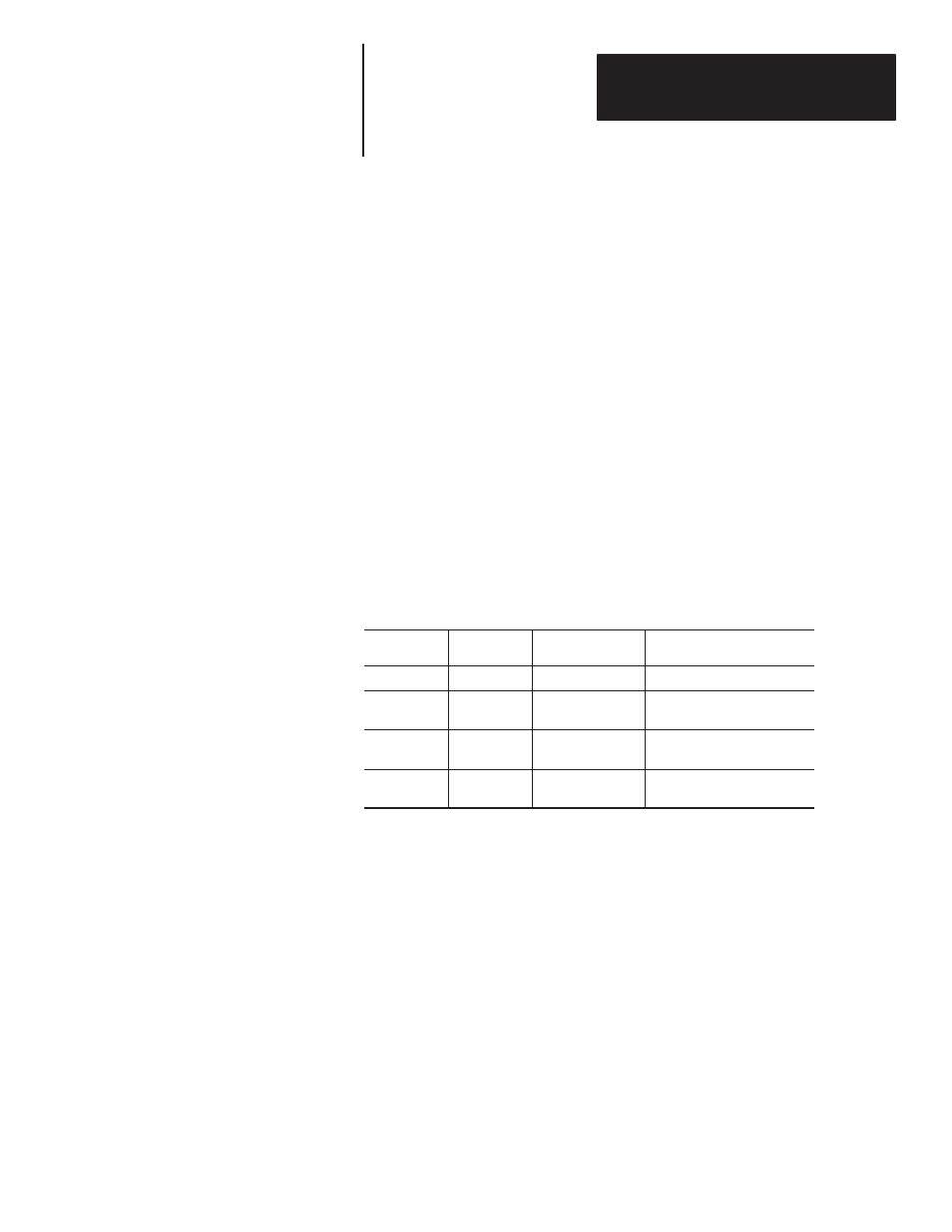
Table 7.D
Strobe Commands
Strobe Line
MS0
Strobe Line
MS1
Name
Strobe Command
0
0
NULL
Ignore Data Lines
1
0
LDAT
Data lines are least significant
byte of variable.
0
1
HDAT
Data lines are most significant
byte of variable.
1
1
MSGA
Data lines are a message
number.
NULL or MSGA
The NULL tells the DL20 to ignore the data lines. The fourth strobe,
MSGA, tells the DL20 to put the value of the data lines into the message
queue.
LDAT
LDAT means the least significant byte of a variable is being strobed in.
Variables are usually sixteen bits in size or four BCD digits long. Since there
are only ten (eight used for variable data) wires in the data group, the
variable must be strobed over in two steps. The two values strobed in are
then added together.
HDAT
HDAT means that the most significant byte is being strobed in. The data
lines are interpreted a little differently this time. Table 7.E shows how the
data lines are interpreted using binary values. Table 7.F shows the values
when using BCD values.