Rockwell Automation 2706 DL20 SERIES G USER MANUAL User Manual
Page 75
Chapter 7
The Parallel Port
7–3
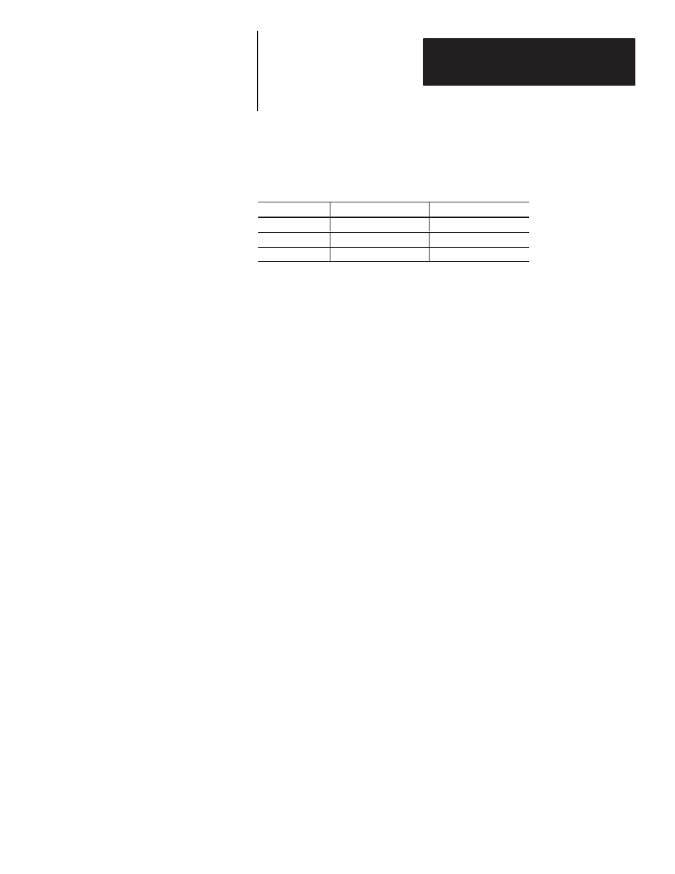
Table 7.A
Voltage Levels for Each Logic State
(Typical Input Resistance = 10K Ohms)
Voltage Range
Low True Logic Value
High True Logic Value
0-1.5 VDC
1 or ON
0 or OFF
1.5 - 3.5 VDC
Indeterminate
Indeterminate
3.5 - 30 VDC
0 or OFF
1 or ON
As Table 7.A illustrates, the DL20 can accept high true (higher voltage
level=1) or low true (lower voltage level=1) logic. Chapter 8 explains how
to set parallel port logic levels. Choose whichever logic level best suits your
application.
Note: The Allen-Bradley TTL Output Module (1771-OG), DC Output
Module (1771-OB), or AC Output Module (1771-OA) can be used to drive
the parallel port.
Binary vs. BCD
You can use separate data modes for input message triggers and variables
when using the parallel port. Message triggers can be in binary and variable
data can be in BCD or vice versa. This means you could input variables in
BCD format, which may be easier to use, and the message triggers could be
in binary, which provides access to the full 1022 message capacity. Select
the data modes using the special functions menu as described in Chapter 8.
Each numbering system, binary or BCD, has its own merits. Your choice
will often be based on the format used by the host. However, binary values
provide certain advantages:
•
Range of binary message triggers is from 1 - 1022.
Range of BCD message triggers is from 1 - 399.
•
Variable range for binary values is -32,768 through 32,767.
Variable range for BCD values is 0 through 9,999.
Also, it is not possible to represent negative numbers using BCD format.