6 - the serial port, Chapter objectives, Serial port connectors – Rockwell Automation 2706 DL20 SERIES G USER MANUAL User Manual
Page 66: The serial port, Chapter objectives serial port connectors
A–B
6
Chapter
6–1
The Serial Port
This chapter describes the serial port of the DL20. You can use the serial
port to send or receive data using RS-232 or RS-422 standards. It describes:
•
Serial port connectors
•
How to connect devices to the serial port
•
Serial port data formats
•
Addressable master feature
•
Slave displays
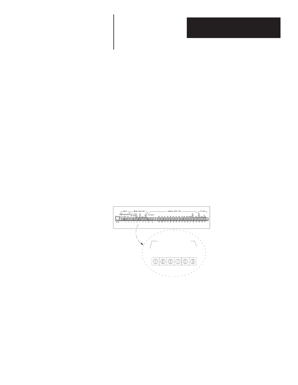
Figure 6.1 shows the serial port connectors of the DL20. All serial port
connectors are optically isolated from the main circuitry in the DL20.
Figure 6.1
Serial Port Connectors
RS
422
+
RS
232
OUT
RS
232
IN GND
+12
VDC
OUT
SERIAL COMM PORT
RS
422
-
4
5
6
7
8
9
➀
Terminal
Function
4, 5
Send or Receive RS-422 Data
6
RS-232 Data Output
7
RS-232 Data Input
8
RS-232 Common
9
+12 VDC asserts certain RS-232 Handshake Lines,
on terminals or printers. Do not use as a power source.
➀
Cable shields should terminate at terminal 8 (Common).
See Chapter 9 for
wiring connections.
Terminals 4 and 5 send and receive RS-422 data.
Terminal 7 is the RS-232 input and terminal 6 is the output.
Terminal 8 is RS-232 common; all cable shields are terminated here.
Terminal 9 is a +12 VDC output for asserting handshake lines on some
printers or terminals. Do not use this output as a power source. There is a
plastic cover over terminal 9 to prevent inadvertent connections.
Chapter Objectives
Serial Port Connectors