Dl20 wiring terminals, Chapter 9 installation and maintenance, Figure 9.1 dl20 connection terminals – Rockwell Automation 2706 DL20 SERIES G USER MANUAL User Manual
Page 114
Chapter 9
Installation and Maintenance
9–3
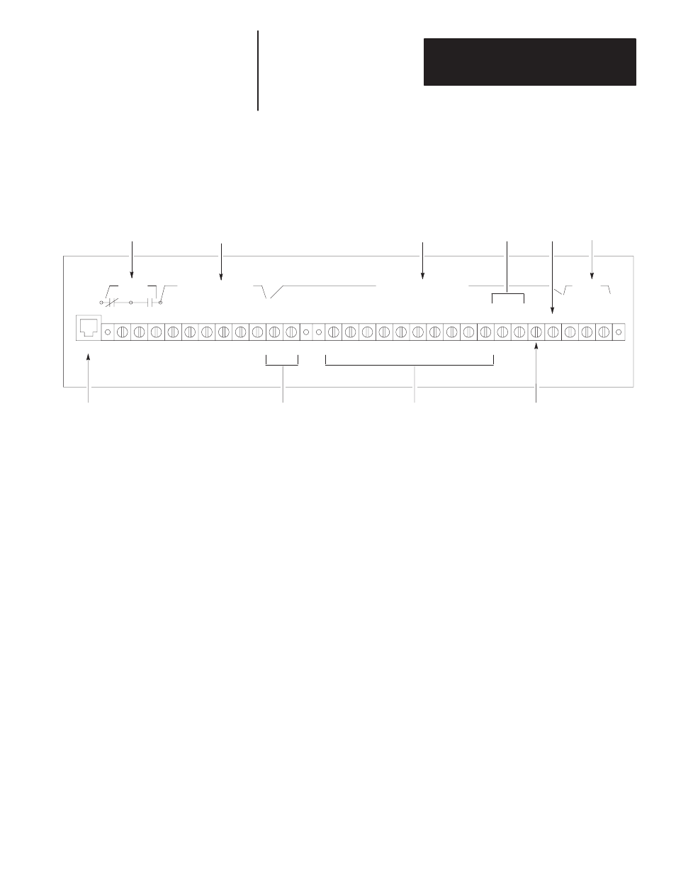
DL20 Wiring Terminals
Figure 9.1
DL20 Connection Terminals
KY BD
1
2
3
4
5
6
7
8
9
10
11
RS
422
-
RS
232
OUT
+12
VDC
OUT
ETS
-
ETS
+
E.
GND
RELAY
SERIAL COMM PORT
PARALLEL INPUT PORT
AC PWR
MS1 MS0
+5
VDC
OUT GND
VAC
HOT NEU
RELAY
KYBD
SERIAL COMM PORT
PARALLEL INPUT PORT
AC PWR
D9-D0
+5VDC OUT
ETS
11A
11B
12
13
14
15
16
17
18
19
GND
MS0 MS1
D9
D8
D7
D6
D5
D4
D3
D2
D1 D0
N.C. COM N.O.
RS
422
+
RS
232
IN GND
RELAY
(Terminals 1, 2, and 3). Relay is switched whenever specified messages are
displayed. It can be used, for example, to sound a horn and alert an operator
to read the display. The relay contacts are rated for 3 Amperes at 250 VAC
or 30 VDC.
KYBD
This input connector connects optional keyboards (Catalog No. 2706-NK1,
-NK2).
Important: Only the 2706 keyboards may be plugged into this port. All
other programming keyboards must be connected to the SERIAL COMM
PORT.
SERIAL COMM PORT
(Terminals 4 thru 9). The DL20 is capable of two communication protocols
on the SERIAL COMM PORT.
•
RS-422 interface on terminals 4 and 5 is typically used to send data to
remote displays or a printer. These devices may be up to 4,000 feet away.
•
RS-232 output (terminal 6) can be connected to a printer. RS-232 input
(terminal 7) can be used to program the DL20 or trigger messages. The
GND connection (terminal 8) doubles as an RS-232 common and a shield
ground. The +12 VDC (terminal 9) is for tying RS-232 handshake lines
high. DO NOT USE for any other purpose.
Data recorders, for storing messages on tape, are also connected to the
RS-232 port.