Plc output/dl20 input signals, Plc output / dl20 input signals – Rockwell Automation 2706 DL20 SERIES G USER MANUAL User Manual
Page 175
Appendix H
Parallel Input Converter
H–3
You will need to configure the parallel port to communicate with the input
converter and determine the timing for data transfers between the DL20 and
the converter.
Use the instructions below to set up the DL20 parallel port for operation with
Series A, B, C or later Parallel Input Converters.
1. Select the AC input mode of the parallel port when programming the
DL20. You can do this by accessing the special function Set Up I/O Ports
and answering appropriately to the prompt USE NG 1/2 SER A,B?
Answering Yes to this prompt selects an AC sampling method.
Answering No selects a DC sampling method.
2. Select a scan rate of 28 (default) for AC sampling with Parallel Input
Converters (Catalog No. 2706-NG1, -NG2 Series A, B, C or later). The
scan rate is used to determine the minimum amount of time that stable
data must be present on the input terminals of the AC converter to allow
for two samples of the parallel port.
3. If the Parallel Input Converter (Catalog No. 2706-NG1, -NG2 Series C or
later) is used, the debounce value must also be specified. Use the value of
25 ms for the debounce.
Minimum Data Hold Times (MDHT) values listed below are based on a scan
rate of 28.
Series A or B Converter MDHT = 180 ms
Series C and Later Converter MDHT = 100 ms
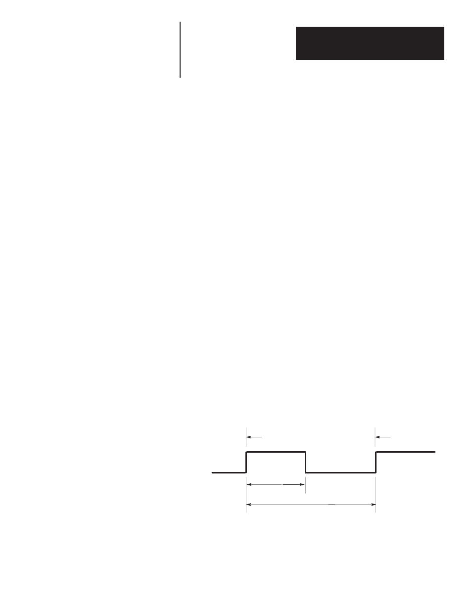
The following diagram shows the relationship between Minimum Data Hold
Times (MDHT) and Minimum Time Between Messages (MTBM).
Timing Diagram
5 - 30VDC
0VDC
Start of Message 1
Start of Message 2
MDHT
MTBM
PLC Output /
DL20 Input Signals