Describing the hardware – Rockwell Automation DeviceNet SEMINAR LAB EX User Manual
Page 5
DeviceNet Seminar Lab Exercises
5
Publication 1787.6.1 - August 1997
Describing the
Hardware
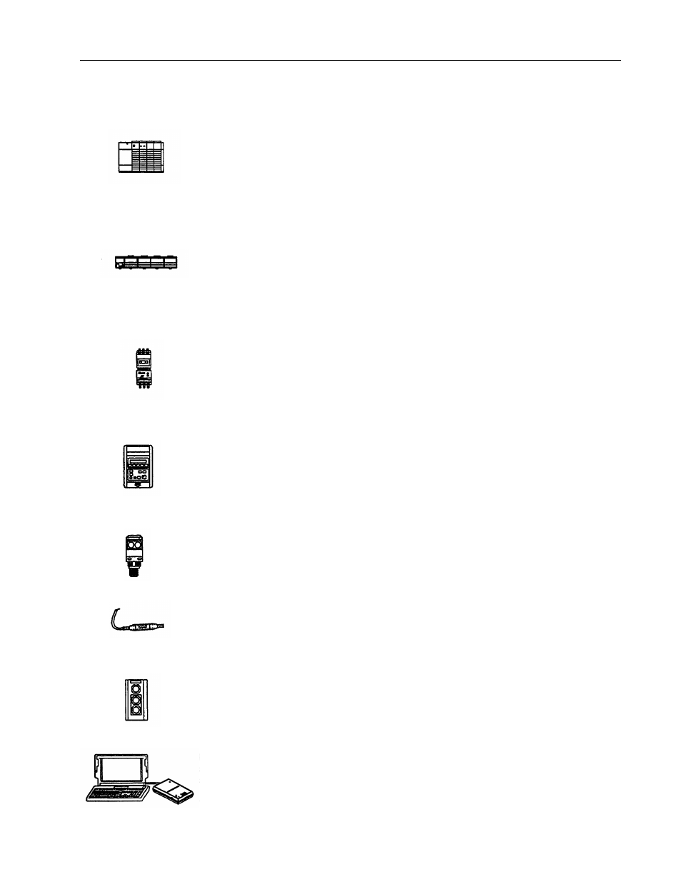
Here are the descriptions and the node numbers of the devices contained in
the demo boxes
.
•
An I/O chassis with an SLC
TM
500 processor and a 1747-SDN scanner
Scanner node number = 00
The scanner is the DeviceNet master coordinating all control data to and from all devices
on the DeviceNet network. This DeviceNet data is transferred to and from the SLC 500
processor via M1/MO and discrete I/O transfers. This data is then used in the SLC 500
ladder program to do the actual control logic.
•
A 1794-ADN FLEX I/O
TM
adapter connected to an analog output module and a discrete
input module.
Adapter node number = 02
Analog output channel 0 is connected to a volt meter to easily display the voltage output.
Also a 4-position selector switch is connected to bits 0-3 of the 1794-IB16 discrete input
module.
•
An SMP-3
TM
solid-state overload relay connected to the DeviceNet network via a 1203-
GK5 communication module.
SMP-3 solid state overload relay node number = 03
The SMP-3 solid-state overload relay provides solid-state motor overcurrent protection
in addition to ground fault protection, jam/stall protection, and protection against damage
caused by phase loss conditions.
•
A 1305 ac drive connected to the DeviceNet network via a 1203-GK5 communication
module.
1305 ac drive node number = 04
The 1305 ac drive provides drive status and diagnostic data at the local panel using the
part of the drive known as the Human Interface module or at a supervisory control station
over DeviceNet5/03.
•
A Series 9000 PHOTOSWITCH
TM
photoeye.
Photoeye node number = 07
The Series 9000 photoeye is designed to withstand harsh environments. The sensor for
this lab is retroflective.
•
A DeviceLink
TM
discrete I/O connected to a limit switch.
DeviceLink discrete I/O node number = 10
The DeviceLink discrete I/O connects single non-DeviceNet dc source devices to the
DeviceNet network.
•
A 2705T RediSTATION
TM
operator interface.
2705T RediSTATION operator interface node number = 15
The RediSTATION operator interface is a pushbutton station that has a start button, a
stop button, and a red pilot light.
•
1787-MGR DeviceNetManager
TM
software, version 3.001 connected to the DeviceNet
network via a 1770-KFD interface module.
Software node number = 62
DeviceNet Manager
software configures software parameters of DeviceNet devices
from multiple vendors and performs network diagnostics and troubleshooting.