Ground the scanner, Panel mounting -4, Ground the scanner -4 – Rockwell Automation 1753-DNSI DeviceNet Safety Scanner for GuardPLC Controllers User Manual
Page 24: Panel mounting
Publication 1753-UM002A-EN-P - July 2005
2-4 Install the 1753-DNSI
Panel Mounting
Mount the scanner directly to a panel using 4 screws. The preferred
screws are #8 (M4); however, #6 (M3.5) may be used.
1. Use the mounting template provided in the module’s installation
instructions, publication number 1753-IN009.
2. Space your module properly to allow for adequate cooling. See
3. Secure the template to the mounting surface.
4. Drill holes through the template.
5. Remove the mounting template.
6. Secure the module to the panel using 4 screws.
Ground the Scanner
This product is intended to be mounted to a well grounded mounting
surface such as a metal panel. Refer to the Industrial Automation
Wiring and Grounding Guidelines, publication 1770-4.1, for additional
information.
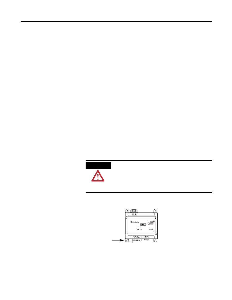
Functionally ground the module through its DIN rail connection or
through the mounting foot, if panel-mounted.
You must always connect the power supply functional ground screw
when connecting the power supply.
You must provide an acceptable grounding path for each device in
your application. For more information on proper grounding
ATTENTION
This product is grounded through the DIN rail to
chassis ground. Use zinc-plated yellow-chromate
steel DIN rail to assure proper grounding. The use of
other DIN rail materials (e.g. aluminum, plastic, etc.)
that can corrode, oxidize, or are poor conductors,
can result in improper or intermittent grounding.
Grounding Stamping