Understand data signals -3, Understand data signals – Rockwell Automation 1753-DNSI DeviceNet Safety Scanner for GuardPLC Controllers User Manual
Page 13
Publication 1753-UM002A-EN-P - July 2005
Before You Begin 1-3
For safety data, the scanner communicates with safety devices via
cyclic messages only. You configure input and output connections in
the DeviceNet safety scanner to transfer input and output data to and
from DeviceNet safety I/O modules and the GuardPLC controller.
The scanner can make data available to other DeviceNet scanners
using Target connections. When Target connections are enabled, the
safety scanner looks like a standard I/O device that can be added to
another scanner’s scanlist,or a safety target device allowing another
safety scanner to connect to the safety data by adding a safety
connection. This allows for the transfer of data signals between two
GuardPLC controllers for safety interlocking and distributed safety
control. Standard data signals can also be exchanged with PLCs, HMIs,
or a ControlLogix system with a 1756-DNB scanner on the DeviceNet
network. For more information on Target connections, see
Appendix B.
Understand Data Signals
In order to understand how to use data signals from the safety scanner
in your GuardPLC application logic, you must know:
• whether the signal data is regarded as safety or standard data in
the end device, and
• whether the signal data was transferred over a safety connection
or a standard connection.
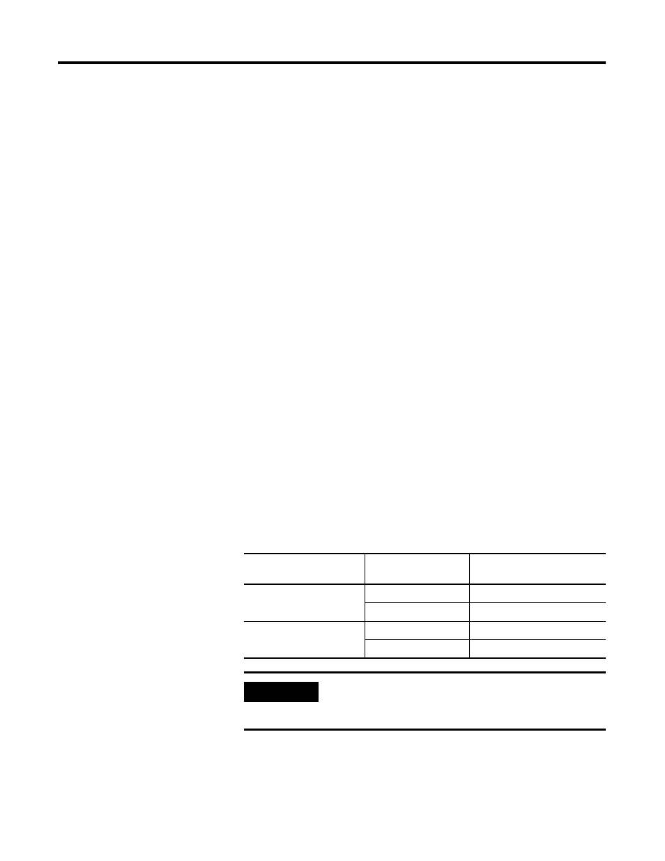
The following table defines permitted uses of safety and standard
signals based on connection and signal type.
End Device Signal
Definition
Connection Type
Permitted Use in Application
Safety Safety
Safety
Standard
Standard
Standard
Safety
Standard
Standard
Standard
IMPORTANT
Only safety signal data transmitted over safety
connections may be used as safety data in safety
application logic.