Power supply heat dissipation graphs – Rockwell Automation 1747-L5xx SLC 500 Modular Hardware Style User Manual User Manual
Page 266
Publication 1747-UM011G-EN-P - June 2008
266
Calculating Heat Dissipation for the SLC 500 Control System
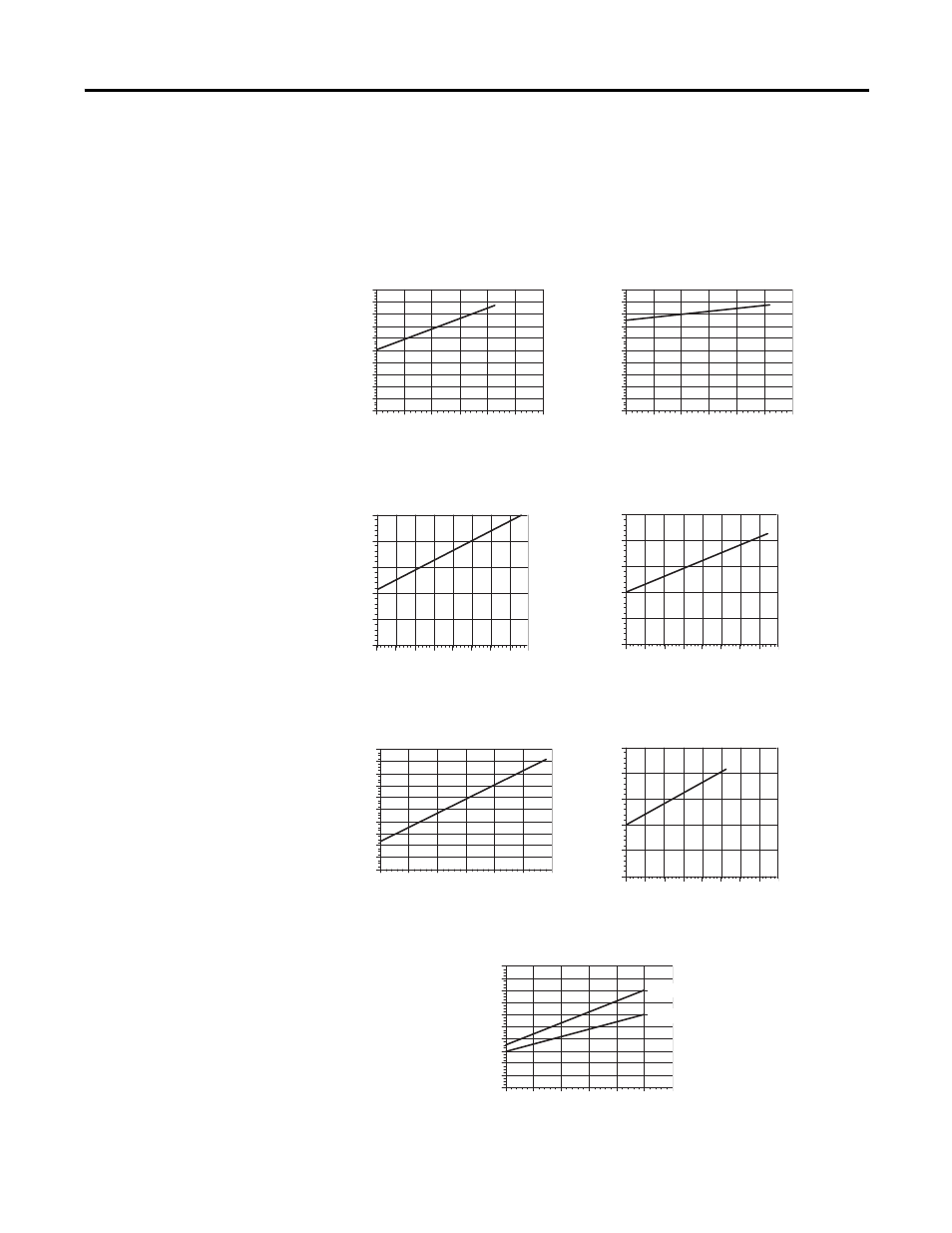
Power Supply Heat Dissipation Graphs
Use the graphs below for determining the power supply dissipation in
step 2 of the Example Worksheet for Calculating Heat Dissipation.
1746-P2
Power Supply Change in Power
Dissipation due to Output Loading
1746-P1
Power Supply Change in Power
Dissipation due to Output Loading
1746-P3
Power Supply Change in Power
Dissipation due to Output Loading
1746-P4
Power Supply Change in Power
Dissipation due to Output Loading
Power Supply Loading (Watts)
Power Supply Loading (Watts)
Power Supply Loading (Watts)
Power Supply Loading (Watts)
1746-P5
Power Supply Change in Power
Dissipation due to Output Loading
Power
Supply Dissipa
tion
(W
at
ts
)
Po
we
r Supply Dissipa
tion
(W
atts)
Power Supply
Diss
ipation (W
atts)
Power Supply
Diss
ipation (W
atts)
Power
Supply Dissipa
tion
(W
at
ts
)
Power Sup
ply Dissipation (W
atts)
Power Supply Loading (Watts)
Power Supply Loading (Watts)
1746-P6
Power Supply Change in Power
Dissipation due to Output Loading
1746-P7
Power Supply Change in Power
Dissipation due to Output Loading
Power Supply Loading (Watts)
20
18
16
0
14
12
10
8
6
4
2
0
5
10
15
20
25
30
0
10
20
30 40 50
60
0 5 10 15 20 25
35
0 10 20 30 40 50 60
0 10 20 30 40 50 60
0
10
20
30
40
50
60
0
20
40
60
80
100
70 80
20
18
16
0
14
12
10
8
6
4
2
20
18
16
0
14
12
10
8
6
4
2
20
18
16
0
14
12
10
8
6
4
2
25
20
15
10
5
0
25
20
15
10
5
0
25
20
15
10
5
0
Power Sup
ply Dissipation (W
atts)
Po
wer Supp
ly Dissipation
(W
atts)
Po
wer Supp
ly
Dissipatio
n (W
atts)
24V input
12V input