Powering the link coupler – Rockwell Automation 1747-L5xx SLC 500 Modular Hardware Style User Manual User Manual
Page 196
Publication 1747-UM011G-EN-P - June 2008
196
Setting Up the DH-485 Network
Grounding and Terminating the DH-485 Network
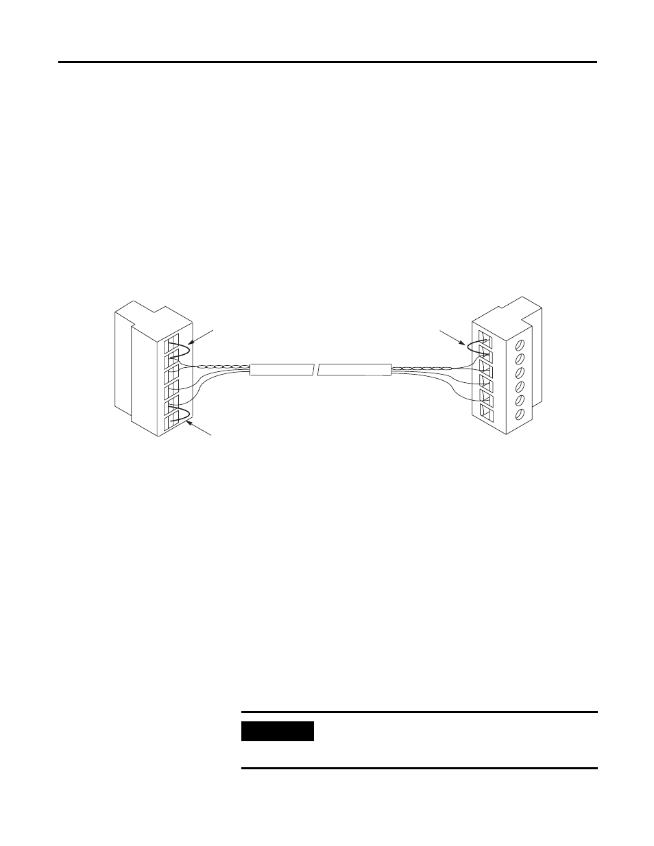
Only one of the link couplers at the end of the link must have
Terminals 1 and 2 of the network connector jumpered together. This
provides an earth ground connection for the shield of the
communication cable.
Link couplers at both ends of the network must have terminals 5 and
6 of the link connectors jumpered together. This connects the
termination impedance (of 120
Ω
) that is built into each link coupler
as required by the DH-485 specification. See the figure below for the
proper jumpering.
End-of-line Termination
Powering the Link Coupler
In normal operation with the programmable controller connected to
the link coupler, the processor powers both the link coupler and
peripheral device (DTAM, PIC) if connected through the 1747-C11
cable.
If you do not connect the processor to the link coupler, then use a
24V dc power supply to power the link coupler and peripheral
device. The 1747-AIC interface requires 85 mA at 24V dc. With a
peripheral device connected, the total current required is 190 mA at
24V dc.
If both the processor and external power are connected to the link
coupler, only the external source is used.
1
2
3
4
5
6
1
2
3
4
5
6
Belden #9842 Cable
1219 m (4000 ft) maximum length
Jumper
Jumper
Jumper
IMPORTANT
Always connect the CHS GND (chassis ground) terminal to the
nearest earth ground. This connection must be made whether or
not an external 24V dc supply is used.