Rockwell Automation 1747-L5xx SLC 500 Modular Hardware Style User Manual User Manual
Page 107
Publication 1747-UM011G-EN-P - June 2008
Installing Your Hardware Components 107
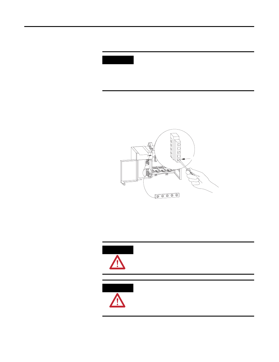
4. Connect the ground screw of the power supply to the nearest
ground or ground bus. Use a #14 AWG 75 Deg. Copper wire
(Category 1 per Industrial Automation Wiring and Grounding
Guidelines, publication 1770-4.1) and keep the leads as short as
possible. The 1746-P4 is shown below.
5. Remove the warning label from the top of the power supply.
6. Connect line power to the power supply.
For the 1746-P1, 1746-P2, 1746-P4, 1746-P5, and 1746-P6 power
supplies, use PWR OUT +24V dc and PWR OUT COM terminals to
IMPORTANT
Terminal screws on the 1746-P1, 1746-P2, 1746-P3, 1746-P5,
1746-P6, and 1746-P7 power supply should be tightened with a
maximum torque of 1 Nm (8.8 lb-in).
Terminal screws on the 1746-P4 power supply should be
tightened with a max torque of 0.8 Nm (7 lb-in).
ATTENTION
If you have a 1746-P3 power supply, see page 64 for special
grounding considerations.
ATTENTION
Your SLC 500 power supply can be damaged by voltage surges
when switching inductive loads such as motors, motor starters,
solenoids, and relays. To avoid damage to your SLC 500 power
supply in these applications, use an isolation transformer to
isolate the power supply from harmful voltage surges.
Chassis Ground
Nearest Ground Bus
Tighten terminal
screws to 0.8 Nm
(7 lb-in)