Install your power supply, Remove the memory module – Rockwell Automation 1747-L5xx SLC 500 Modular Hardware Style User Manual User Manual
Page 104
Publication 1747-UM011G-EN-P - June 2008
104
Installing Your Hardware Components
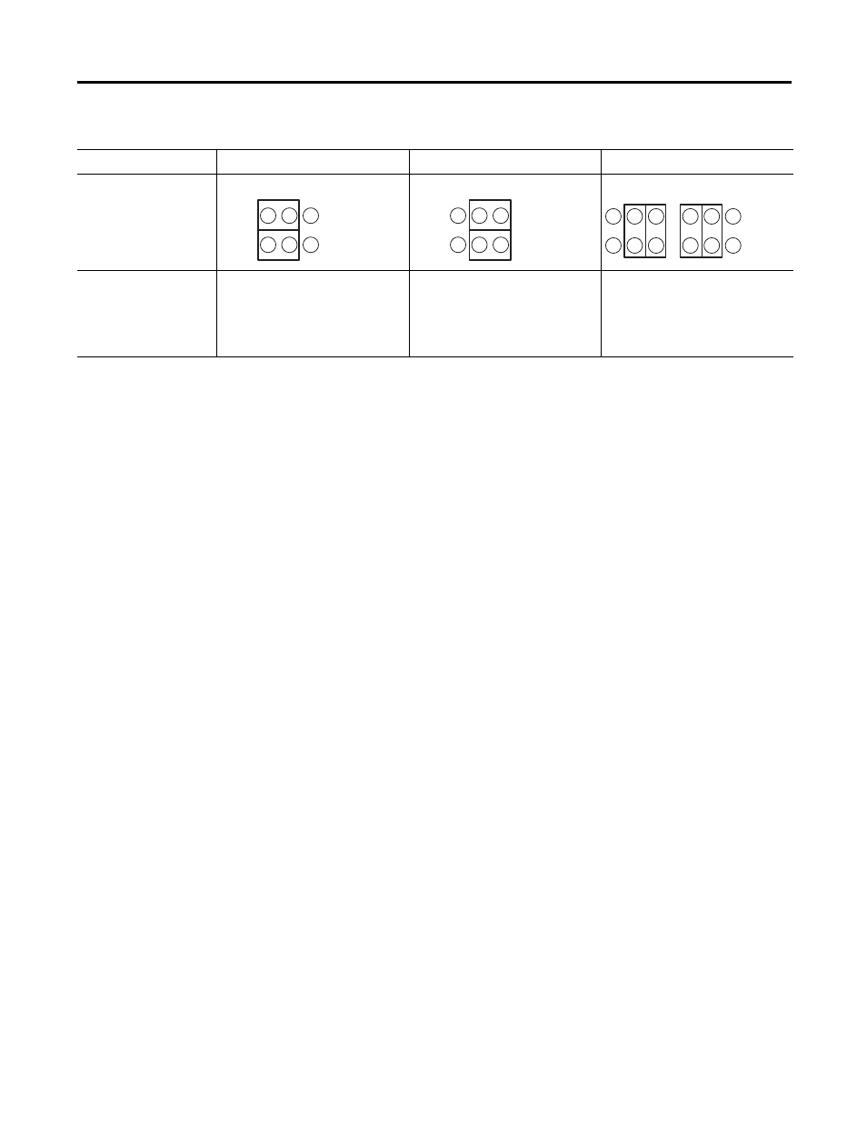
3. Place jumper J1 as shown below.
4. Install the processor module into the chassis.
5. Restore power to the controller.
Remove the Memory Module
Follow this procedure to remove the memory module.
1. Remove power and pull out the processor.
2. Grasp the carrier tabs (or connector for the SLC 5/03, SLC 5/04,
and SLC 5/05 processor) with your thumb and index fingers,
then gently but firmly lift upwards on either end of the memory
module carrier.
3. When the end is partially raised, begin lifting the other end in
the same manner. Repeat this until the memory module has
been completely removed from the socket.
Install Your Power Supply
If you have multiple chassis configurations, install the chassis
interconnect cable before installing the power supply.
See Install Your Chassis Interconnect Cable on page 108.
Also, the power supply terminals accept two 2 mm
2
(#14 AWG) wires
and are marked as shown in the figure on page 106.
Processor Type
1747-M1, -M2, -M3
1747-M4
Invalid Settings
1747-L514, 1747-L524
1747-L511, 1747-L531,
1747-L532, 1747-l533,
1747-L541, 1747-L542,
1747-L543, 1747-L551,
1747-L552, 1747-L553
No Jumper J1
No Jumper J1
No Jumper J1