General compactlogix messaging guidelines, General compactlogix messaging guidelines -4 – Rockwell Automation 1761-NET-ENIW MicroLogix Ethernet Interface (ENI) User Manual User Manual
Page 96
Publication 1761-UM006E-EN-P - August 2005
8-4 Connecting CompactLogix Controllers on Ethernet
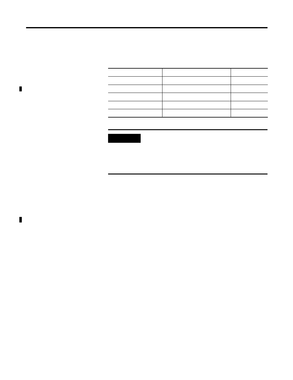
For this example, we will assign the following IP addresses to the
devices on Ethernet:
General CompactLogix
Messaging Guidelines
Rungs 0 and 1, shown in Figure 8.2, of the CompactLogix controller’s
ladder program show an example of throttling two message (MSG)
instructions. In this case, sending a MSG to the SLC 5/05, and then
when it’s complete (Done bit set), initiating a MSG to the
1756-ENBT/ControlLogix controller and so on. The two MSG
instructions toggle, with only one outstanding MSG at a time.
This is recommended for the CompactLogix controller to keep the
amount of user memory needed for incoming and outgoing messages
to a minimum. Each message requires approximately 1.1K bytes of
user memory, allocated when the message is to be sent or received. If
two messages were enabled at the same time, 2.2K bytes of user
memory would need to be available.
Table 8.1 Example IP Addresses for Ethernet Devices
Device
Node Address (for L20 MSG)
IP Address
SLC-5/05
1
131.200.50.92
1756-ENBT
45
131.200.50.93
1761-NET-ENI #2
N/A
131.200.50.94
1761-NET-ENI #1
N/A
131.200.50.95
Computer Ethernet Card
N/A
131.200.50.96
IMPORTANT
The IP addresses in Table 8.1 were arbitrarily
assigned for this example and should only be used
on an isolated Ethernet network as in this example.
Contact your system administrator for unique IP
addresses if you are connecting your Ethernet
devices to your company’s Ethernet network.