Rockwell Automation 1761-NET-ENIW MicroLogix Ethernet Interface (ENI) User Manual User Manual
Page 63
Publication 1761-UM006E-EN-P - August 2005
ENI/ENIW Configuration (Nodes 241 to 254) 4-23
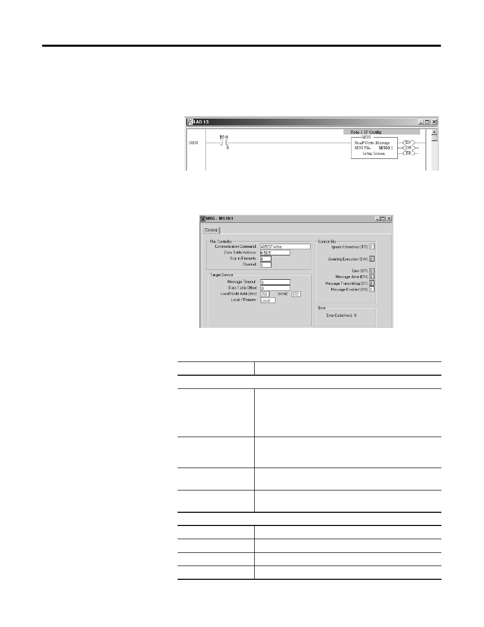
2. Create your message logic using whatever conditional
instructions you may need. In this MicroLogix example, bit
B3:0/8 is used to condition the message instruction and message
file 10, element 1 is used to manage the message session.
3. Open the message instruction and enter the appropriate
variables. The variables are described in Table 4.9.
Table 4.9 Message Instruction Variables for Configuring ENI/ENIW Data
Parameters
Variable
Setting
This Controller Parameters:
Communication
Command
For the ENI/ENIW configuration, this must be set to:
• 485CIF for MicroLogix and SLC
• a PLC2 Unprotected Write command for CompactLogix
and PLC-5
Data Table Address
In this example we are using integer file 50, element 5
(instruction starts at N50:5) to set the ENI/ENIW’s IP address to
195.100.100.1.
Size in Elements
For all ENI/ENIW TCP/IP data configuration, always set this to
4 (4 words).
Channel
The RS-232 communication channel that is connected to the
ENI/ENIW, typically 0 or 1.
Target Device Parameters:
Message Timeout
Leave this value at the default.
Data Table Offset
Always 0.
Local Node Addr (dec).
This is the destination node address, in this example it is 101.
Local/Remote
Always Local.