External power supply wiring, Mounting, External power supply wiring -3 mounting -3 – Rockwell Automation 1761-NET-ENIW MicroLogix Ethernet Interface (ENI) User Manual User Manual
Page 25: External power supply wiring mounting
Publication 1761-UM006E-EN-P - August 2005
Installation and Wiring 2-3
External Power Supply
Wiring
Mounting
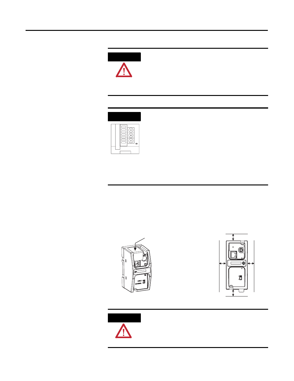
The ENI/ENIW must be mounted in the vertical position, as shown.
Horizontal mounting is not recommended due to thermal considerations. Allow 50 mm
(2 in.) of space on all sides for adequate ventilation. See page A-1 for
operating temperature specification.
WARNING
EXPLOSION HAZARD
In Class I Division 2 applications, an external, Class 2
power supply must be used. The DC Power Source
selector switch on the ENI/ENIW must be set to
EXTERNAL before connecting the power supply to
the ENI/ENIW.
IMPORTANT
• In non-hazardous locations, external power is not
required. Some devices (such as a MicroLogix
controller) provide power to the ENI/ENIW via a
cable connected to the ENI/ENIW’s port 2. Be
sure to set the DC power source selector switch
to match your particular configuration, CABLE or
EXTERNAL.
• Always connect the CHS GND (chassis ground)
terminal to the nearest earth ground. This
connection must be made whether or not an
external 24V dc supply is used.
VDC
24
DC
NEUT
CHS
GND
Bottom View
ATTENTION
Do not remove the protective debris strip until after
all the equipment in the panel is mounted and wiring
is complete. Once wiring is complete, remove the
protective debris strip. Failure to remove strip before
operating can cause overheating.
protective debris strip
ETHERNET
FAULT
RS232
TX/RX
PWR
CABLE
EXTERNAL
IP
top
bottom
side
side