Autotune update system inertia – Rockwell Automation 1395 ControlNet Communication Board User Manual
Page 46
3–32
Configuration & PLC Interfacing
Publication 1395–5.37– March, 1999
Autotune Update System Inertia
This function updates the Drives internal database with the system
inertia (parameter 703) and the maximum achievable velocity loop
bandwidth (parameter 701) as calculated by the auto tune firmware and
provides the data to the PLC Controller in the PMR message.
PLC Block Transfer Instruction Data –
Write
Read
Size In Elements:
4
8
Processor Type:
PLC-5
PLC-5
Destination Address:
N40:-3
N40:0-7
Message Structure –
Message Header Information:
Word 1: 0
Word 2: 0
Function Code, Word 3: 1037
Write Message Length, Word 4: 8 bytes
0
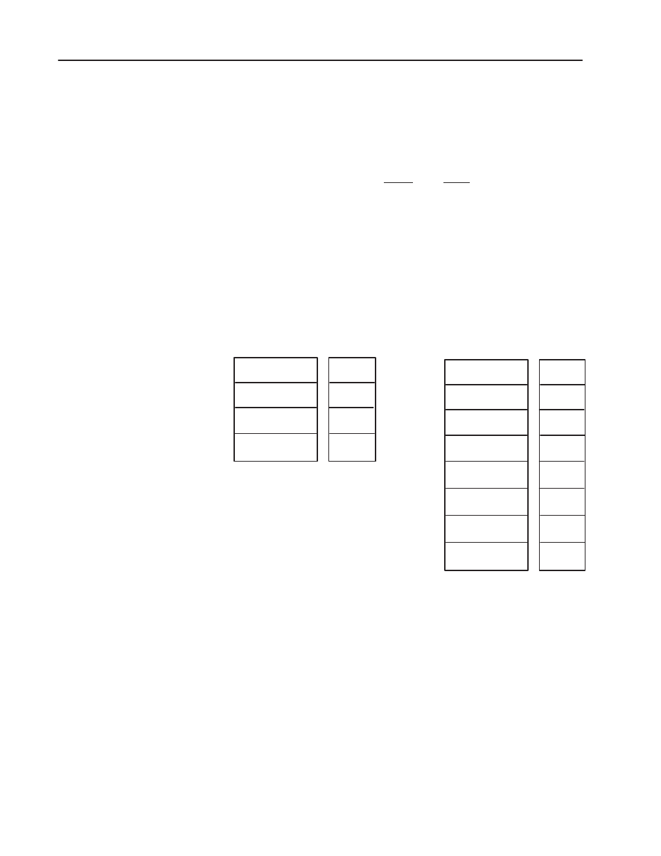
PLC Message Write
PLC Message Read
NOTE:
Word 4 of the PLC Message Read instruction is broken down
into two bytes. The High byte contains the status bits
The Low byte contains the Drive message length in bytes.
Header
Word 1
0
Function Code
1037
Message Length
8 bytes
Header
Word 2
Header
Word 3
Header
Word 4
0
Header
Word 1
0
Function Code
1037
See Note
Header
Word 2
Header
Word 3
Header
Word 4
Data
Word 5
Data
Word 6
Parameter
701
Parameter
Data
Parameter
703
Parameter
Data
Data
Word 7
Data
Word 8
Message Operation – The AUTOTUNE UPDATE SYSTEM
INERTIA function updates the Drives internal database with the
system inertia (parameter #701) and maximum achievable bandwidth
(Parameter #703) as calculated by the autotune firmware, and provides
the data to the PLC Controller.