Introduction & product description, Chapter objective, General board description – Rockwell Automation 1395 ControlNet Communication Board User Manual
Page 11: Led indicators, Chapter
Chapter
2
Publication 1395–5.37 – March, 1999
Introduction & Product Description
Chapter Objective
This chapter contains a description of the major hardware components
of the ControlNet Adapter board. It is not intended to be an all
encompassing technical description of each hardware component. This
chapter provides information to aid service personnel in:
S Identifing the CNA board.
S Understanding the hardware content of the board.
S Understanding the hardware requirements necessary to interface this
board with external devices.
General Board Description
The CNA board contains the hardware necessary to connect the 1395
Drive to ControlNet 1.5. Once connected, this network can be used to
control, diagnose, and setup the Drive. Figure 2.1 shows the major
hardware components located on this board. Refer to Figure 2.1 when
attempting to identify the various hardware components.
The CNA board contains a small interface board, referred to as
the Interface Plug, which contains the hardware necessary to
communicate to PLC controllers via ControlNet. Refer to the
installation section of this manual for further details.
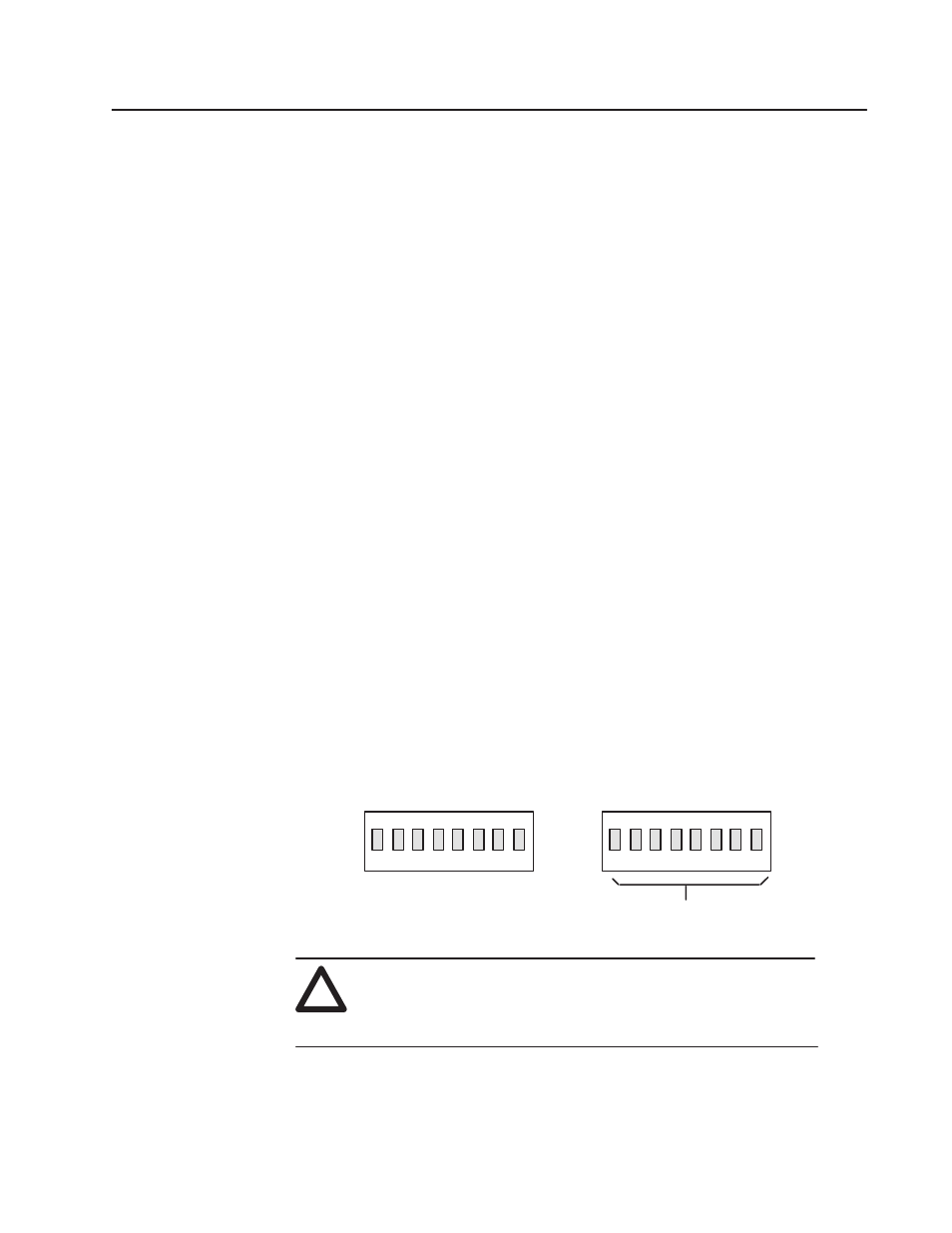
DIP switch U6 is used to select the node address for the ControlNet
adapter.
NOTE: Switches U5, U14 and U15 are physically present on the CNA
board but are inactive in this application.
U5 (Not Active)
U14 (Not Active)
1
2
3
4
5
6
7
8
1
2
3
4
5
6
7
8
U6 (Node Address)
U15 (Not Active)
ControlNet Node #
(1 – 99)
!
ATTENTION: Certain procedures in this manual require that
the Drive “Not be running”. This assumes that the main
contactor is de-energized and that the user has properly set up
the interface logic to meet this criteria.
LED Indicators
The CNA board contains several LED’s used to provide status
information. LED DS1 indicates whether the CNA board itself is