Rockwell Automation 20-COMM-K CANopen Adapter User Manual
Page 32
3-6
Configuring the Adapter
20-COMM-K CANopen Adapter User Manual
Publication 20COMM-UM012B-EN-P
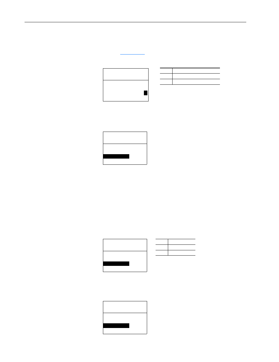
4. Set Parameter 25 - [COS Status Mask] for the bits in the Logic Status
word that should be checked for changes. The bit definitions for the
Status Mask will depend on the drive to which the adapter is connected.
Refer to
Appendix D
or the drive documentation.
Figure 3.6
Example COS Status Mask LCD HIM Screen
5. Set Parameter 26 - [COS Fdbk Change] for the amount of change to
the Feedback that is required to trigger a Change of State message.
Figure 3.7
Example COS Fdbk Change LCD HIM Screen
Using Cyclic Data Exchange
With cyclic data exchange, a PDO is sent periodically.
1. With the CANopen configuration tool, set the transmission mode of the
TPDO1 (Transmit PDO) of the adapter to “0” (synchronous) or “254”
(asynchronous).
2. Set Parameter 24 - [PDO1 Trigger] to “1” (Cyclic).
Figure 3.8
Example DPO1 Trigger LCD HIM Screen
3. Set Parameter 27 - [Cyclic Interval] for the desired time interval
between two transmissions.
Figure 3.9
Example Cyclic Interval LCD HIM Screen
Value Description
0
Ignore this logic bit. (Default)
1
Use this logic bit.
Port 5 Device
20-COMM-K
Parameter #: 25
COS Status Mask
x x x x x x x x x x x 0 0 0 0
1
Bit 0
b00
Default = 1
Port 5 Device
20-COMM-K
Parameter #: 26
COS Fdbk Change
1
1 <> 4294967295
Port 5 Device
20-COMM-K
Parameter #: 24
PDO1 Trigger
1
Cyclic
Value Trigger
0
COS (Default)
1
Cyclic
Port 5 Device
20-COMM-K
Parameter #: 27
Cyc Interval
0.02
s
0.02 <> 655.35
Default = 0.02 s