Setting the – Rockwell Automation 20-COMM-K CANopen Adapter User Manual
Page 18
2-2
Installing the Adapter
20-COMM-K CANopen Adapter User Manual
Publication 20COMM-UM012B-EN-P
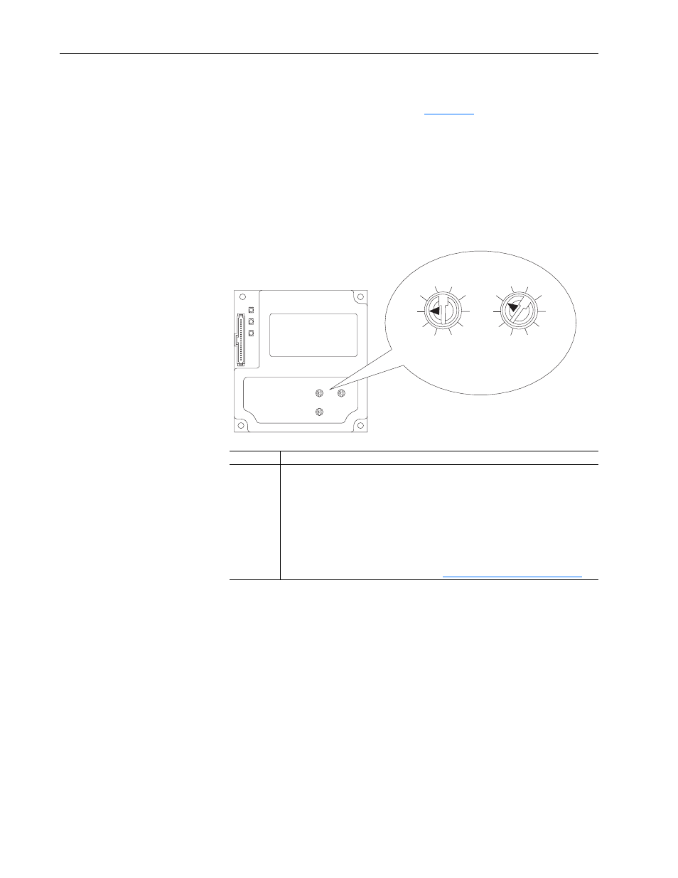
Setting the Node Address Switches
Set the adapter Node Address switches (
) by rotating the switches
to the desired value for each digit.
Important: Each node on the network must have a unique address. Set the
node address before power is applied because the adapter uses
the node address it detects when it first receives power. To
change a node address, you must set the new value and then
remove and reapply power to (or reset) the adapter.
Figure 2.1
Setting Adapter Node Address Switches
The Node Address switch settings can be verified by viewing Parameter 04
- [COPN Addr Actual] using a PowerFlex 7-Class HIM, DriveExplorer
software, or DriveExecutive software.
Setting
Description
00…99
Node address used by the adapter if switches are enabled. The default switch setting is
01. Node address 01 is also the default address used by all uncommissioned devices.
We recommend that you do not use this address as the final adapter address.
The Node Address switches are checked during start-up and, if the address needs to
be changed, the power must be cycled for the change to take effect.
Important: If both Node Address switches are set to “0,” the adapter uses the
Parameter 03 - [COPN Addr Cfg] setting for the node address. With this parameter,
the node address can be set from 1…127. This parameter is readable/writable over the
network, and its default setting is 1. Refer to
Setting the Node Address on page 3-3
Tens
Digit
Ones
Digit
2
1
0
9
8
3
4
5
6
7
2
1
0
9
8
3
4
5
6
7