Care and use manual – Waters SunFire Columns User Manual
Page 9
[ Care and Use ManUal ]
9
1. Remove column.
2. Use acetonitrile as mobile phase A, and acetonitrile with 0.05
mg/mL uracil as mobile phase B (eliminates non-additive mixing
and viscosity problems).
3. Set UV detector at 254 nm.
4. Use the flow rate in the original method and the intended flow
rate on the target instrument.
5. Collect 100% A baseline for 5 minutes.
6. Program a step change at 5 minutes to 100% B, and collect data
for an additional 5 minutes.
7. Measure absorbance difference between 100% A
and 100% B.
8. Measure time at 50% of that absorbance difference.
9. Calculate time difference between start of step
and 50% point.
10. Multiply time difference by flow rate.
VII. addItIonal InFormatIon
a. use of narrow-bore (<3.0 mm i.d.) Columns
This section describes how to minimize extra column effects
and provides guidelines on maximizing the performance of
a narrow-bore column in an HPLC system. A 3.0 mm i.d.
narrow-bore column usually requires no system modifications.
A 2.1 mm i.d. column, however, requires modifications to
the HPLC system in order to eliminate excessive system
bandspreading volume. Without proper system modifications,
excessive system bandspreading volume causes peak broadening and
has a large impact on peak width as peak volume decreases.
b. Impact of Bandspreading Volume on 2.1 mm i.d.
Column Performance
Note: Flow splitters after the column will introduce additional
bandspreading.
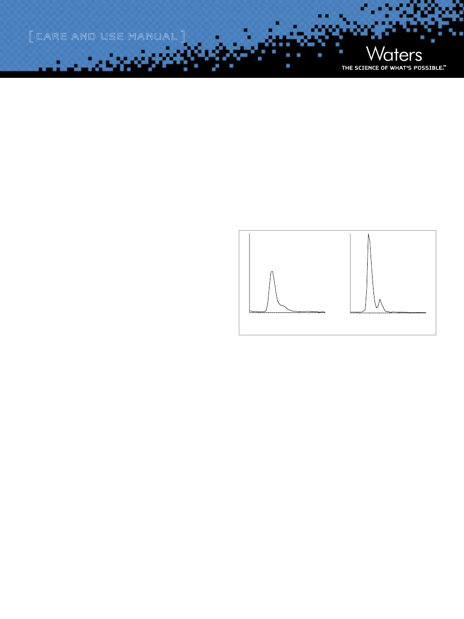
System optimization, especially in a system that contains a flow
splitter, can have dramatic effects on sensitivity and resolution.
Optimization includes using correct-depth ferrules and minimizing
tubing diameter and lengths. An example is given in Figure 10
where system optimization resulted in a doubling of sensitivity and
resolution of the metabolite in an LC/MS/MS system.
7.00
7.50
Non-optimized LC/MS/MS System
Optimized System
8.00
7.00
7.50
8.00
Figure 10: non-optimized vs. optimized lC/mS/mS System
c. non-optimized vs. optimized lC/mS/mS System: Sys-
tem modification recommendations
1. Use a microbore detector flow cell with ≤2.1 mm i.d. columns.
Note: Detector sensitivity is reduced with the shorter flow cell
path length in order to achieve lower bandspreading volume.
2. Minimize injector sample loop volume.
3. Use 0.009 inch (0.25 mm) tubing between pump
and injector.
4. Use 0.009 inch (0.25 mm) tubing for rest of connections
in standard systems and 0.005 inch (0.12 mm) tubing for
narrowbore (2.1 mm i.d.) systems.
5. Use perfect (pre-cut) connections (with a variable depth inlet if
using columns from different suppliers).
6. Detector time constants should be shortened to less than
0.2 seconds.