Process data transfer – Lenze EMF2178IB User Manual
Page 66
Process data transfer
Cyclic process data objects
Mapping in CANopen objects (I−160x, I−1A0x)
l
66
EDSMF2178IB EN 3.0
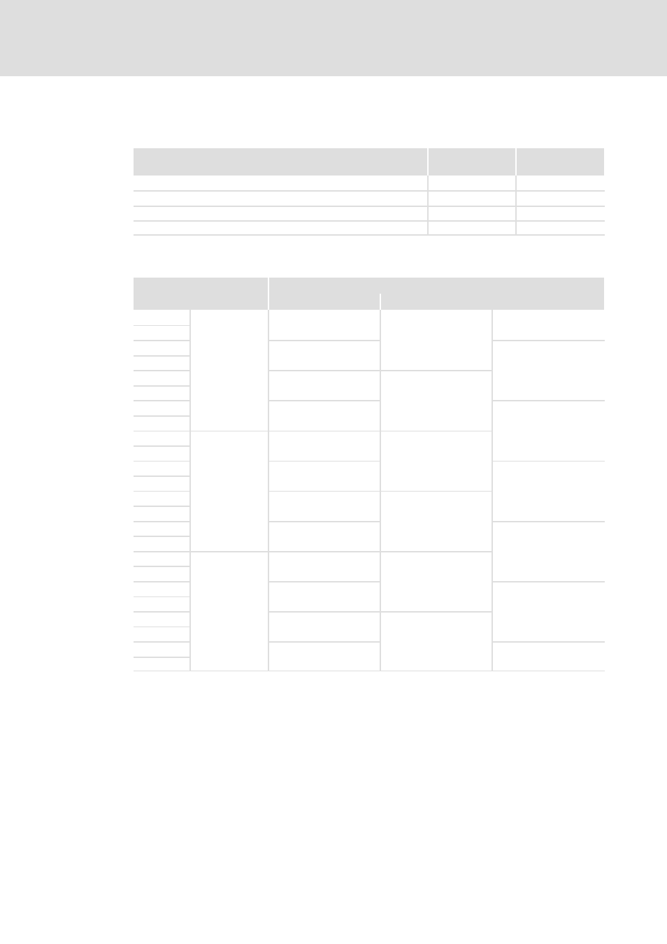
AIF data image in codes
The AIF process data images are mapped to the following codes:
AIF process data
Code
Index
[hex]
Process input data AIF−IN as 16−bit values
C1822/1 ... 12
0x58E1
Process output data AIF−OUT as 16−bit values
C1823/1 ... 12
0x58E0
Process input data AIF−IN as 32−bit values
C1824/1 ... 11
0x58DF
Process output data AIF−OUT as 32−bit values
C1825/1 ... 11
0x58DE
The codes represent the values at the AIF interface. Converted into indices, mapping refers
to these codes.
Process data AIF−IN
Represented as
16−bit values
32−bit values
1)
Byte 1
AIF1−IN
(bytes 1 ... 8)
C1822/1
[C1824/1]
2nd byte
3rd byte
C1822/2
C1824/2
Byte 4
Byte 5
C1822/3
C1824/3
Byte 6
7th byte
C1822/4
[C1824/4]
Byte 8
Byte 9
AIF2−IN
(bytes 1 ... 8)
C1822/5
C1824/5
Byte 10
Byte 11
C1822/6
[C1824/6]
Byte 12
Byte 13
C1822/7
[C1824/7]
Byte 14
Byte 15
C1822/8
[C1824/8]
Byte 16
Byte 17
AIF3−IN
(bytes 1 ... 8)
C1822/9
C1824/9
Byte 18
Byte 19
C1822/10
[C1824/10]
Byte 20
Byte 21
C1822/11
[C1824/11]
Byte 22
Byte 23
C1822/12
Byte 24
1)
[Cxxx/y] = Codes not relevant for the AIF modes
(
¶ 68)