7 alarm connections, Alarm connections – Leica Biosystems PELORIS_PELORIS II User Manual
Page 38
Hardware
Leica PELORIS™ User Manual Rev K © Leica Biosystems Melbourne Pty Ltd 2011
38
2.7
Alarm Connections
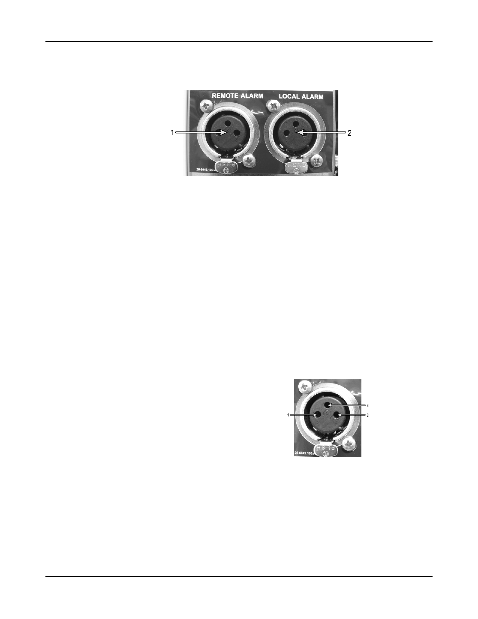
Figure 21. Remote alarm (1) and local alarm (2) connectors
Each Peloris tissue processor has two external alarm connections — a local alarm connection and a
remote alarm connection (see Figure 21). These connections may be used to control a range of
alarm indication devices including audible alarms, visual alarms or automatic phone dialers.
Speak to your service representative to configure the events that will trigger each of the external
alarms, and to set whether the alarms are a single signal or continuous.
Alarm Connector Specifications
The load connected to either alarm connector must not exceed the following specifications.
Alarm Connector Pins
Each alarm connector has three pins as follows (see Figure 22):
Maximum voltage:
30 V DC
Maximum current:
1 A (resistive load)
Maximum current:
0.5 A (inductive load)
Pin 1 — Normally open (item 1)
Pin 2 — Normally closed (item 2)
Pin 3 — Common (item 3)
Figure 22. Alarm connector pins