Clearing field area -49, Replacing faulty sensor(s) -49, 49 kpm iii monitor operation – Kinze 3200 Wing-Fold Planter Rev. 7/14 User Manual
Page 139: Rev. 7/12, Area management
TM
Model 3200
M0241-01
Rev. 7/12
6-49
KPM III Monitor Operation
STEP 4
Turn knob or use arrow keys to highlight faulty
sensor and press F2 key next to Remove.
STEP 5
The following message displays. Select OK to
confirm by pressing knob or Enter key. Select
Cancel to exit.
STEP 6
Unplug sensor and plug in new sensor. Press F1 key
next to Install.
NOTE: Monitor beeps twice when new sensors are learned.
Repeat STEPS 1 through 6 for each faulty sensor
being replaced.
NOTE: Highlighting a sensor and pressing F4 key next to
View displays additional information for troubleshooting
a problem. If a faulty sensor has been ignored it may be
highlighted in list of sensors. Press F3 key next to Revive.
Monitor will try to communicate with sensor. If successful,
‘‘OK’’ displays next to sensor.
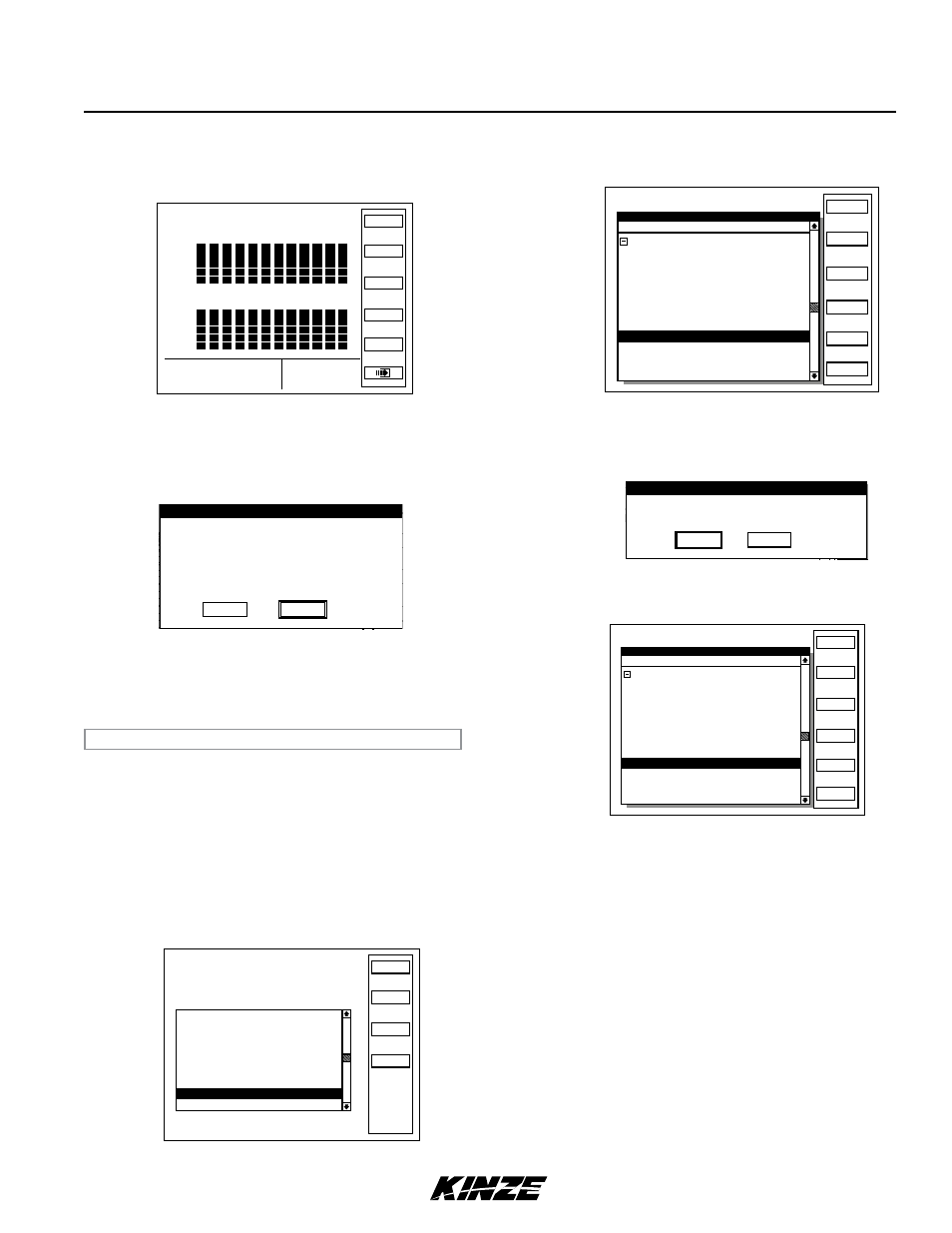
CLEARING FIELD AREA
STEP 1
Display Plant screen to reset counter.
NOTE: If “Area” is not displayed next to F4, press F2 next to “Normal”.
STEP 2
Press F4 key next to Area then press F4 key next to
Clear. A dialog box displays requesting confirmation
to clear.
STEP 3
Highlight “OK” or “Cancel” by turning knob or using
arrow keys. Press knob or Enter key to verify
selection.
NOTE: Only displayed area counter can be cleared.
RowPop
Spacing
Area
Other
Accuracy
Avg
Pop
30618 8.03
1 2 3 4 5 6 7 8 9 10 11 12
1 2 3 4 5 6 7 8 9 10 11 12
120
110
100
90
80
70
60
%
120
110
100
90
80
70
60
%
AC1
Status
Rename
Clr All
Area Management
Total Area
31.3 K
488.37
Clear
Field Area
31.3 K
488.37
Area Counter 1 31.3 K
486.02
Area Counter 2 0.0 K
0.0
Area Counter 3 0.0 K
0.0
Area Counter 4 0.0 K
0.0
Area Counter 5 0.0 K
0.0
Area Counter 6 0.0 K
0.0
Area Counter 7 0.0 K
0.0
Area Counter 8 0.0 K
0.0
Confirm Clear Area
Select and press OK to clear the area counter.
1 Area Counter 1 0.0
Select and press Cancel to retain the value
of the area counter.
Cancel
OK
REPLACING FAULTy SENSOR(S)
NOTE: Monitor beeps twice when new sensors are learned.
STEP 1
Press F6 key until Mode Selection screen appears.
STEP 2
Highlight ‘‘1. Setup Mode’’ by turning knob or using
arrow keys. Press knob or Enter key to display
highlighted item.
STEP 3
Highlight ‘‘9. Sensor Setup’’ by turning knob or using
arrow keys. Press knob or Enter key to display
highlighted item.
Status
Plant
About
Setup Mode
Configuration:
Effective row spacing: 15.0
Front / Rear
1. General Settings
2. Seed Meter Settings
3. Row Unit Alarm Levels
4. Setup Data Logging
5. Configure Planter Monitor
6. Add New Muxbus Sensors
7. Add Single Interplant Row
8. Select Speed Sensor
9. Sensor Setup
10.Calibrate Speed Sensor
Logdata
Setup Mode
Install
Remove
Ignore
Revive
Done
Rear Row 1 OK
Rear Row 2 OK
Rear Row 3
OK
Rear Row 4 OK
Rear Row 5 OK
Rear Row 7 OK
Front Row 1 OK
Front Row 2
OK
Front Row 3 OK
View
Sensor Setup
[Auto Detect]
[Seed Sensors]
Rear Row 6 OK
Rear Row 8 OK
Setup Mode
Install
Remove
Ignore
Revive
Done
Rear Row 1 OK
Rear Row 2 OK
Rear Row 3
OK
Rear Row 4 OK
Rear Row 5 OK
Rear Row 7 OK
Front Row 1 OK
Front Row 2
OK
Front Row 3 OK
View
Sensor Setup
[Auto Detect]
[Seed Sensors]
Rear Row 6 OK
Rear Row 8 OK
Confirm Remove
OK to Remove Rear Row 8?
Cancel
OK
Setup Mode
Install
Remove
Ignore
Revive
Done
Rear Row 1 OK
Rear Row 2 OK
Rear Row 3
OK
Rear Row 4 OK
Rear Row 5 OK
Rear Row 7 OK
Front Row 1 OK
Front Row 2
OK
Front Row 3 OK
View
Sensor Setup
[Auto Detect]
[Seed Sensors]
Rear Row 6 OK
Rear Row 8 none