35 kpm iii monitor operation, Setup mode, Rev. 7/12 – Kinze 3200 Wing-Fold Planter Rev. 7/14 User Manual
Page 125
TM
Model 3200
M0241-01
Rev. 7/12
6-35
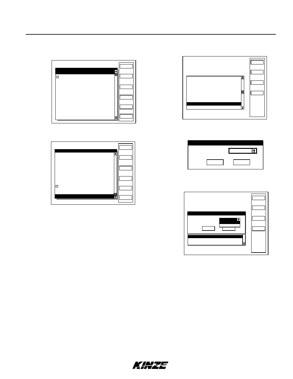
KPM III Monitor Operation
STEP 2
Press F6 key next to Done. Display will return to
Setup Mode screen.
STEP 3
Turn knob or use arrow keys to highlight ‘‘8. Select
Speed Sensor’’ and press knob or Enter key.
STEP 4
Press knob or Enter key to select ‘‘Speed Sensor’’
field. A drop down menu appears.
NOTE: To prevent configuration from being changed select
Cancel, then press rotary encoder knob, Enter key or ESC key.
STEP 5
Turn knob or use arrow keys to highlight “Radar” and
press knob or Enter key.
STEP 6
Turn knob or use arrow keys to highlight “OK” button
and press knob or Enter key.
STEP 7
Plug in Radar, turn knob, or use arrow keys to
advance to “OK”. Press knob or Enter key to save the
information. Display will return to Setup Mode screen.
STEP 8
Press F2 key next to Plant to return to Planter
Configuration screen.
NOTE: Verify distance pulse count is correct for chosen
sensor when switching between speed sensors. There is a
significant distance pulse count variation between radar and
magnetic distance sensors.
STEP 6
Plug in Magnetic Distance Sensor (MDS) and press
F1 key next to Install. Press knob or Enter key to
save information. Sensor Setup screen will appear.
STEP 7
Turn knob or use arrow keys to scroll down to
“Ground Speed Sensor”.
STEP 8
Press F1 key next to Install. Monitor beeps twice to
confirm selection.
STEP 9
Press F6 key next to Done. Display will return to
Setup Mode screen.
STEP 10 Press F2 key by “Plant” to return to Planter
Configuration screen.
NOTE: , verify distance pulse count is correct for chosen
sensor. There will be significant distance pulse count
variation between radar and coil pickup sensors.
Setup Mode
Install
Remove
Ignore
Revive
Done
Rear Row 1 OK
Rear Row 2 OK
Rear Row 3
OK
Rear Row 4 OK
Rear Row 5 OK
Rear Row 6 OK
Rear Row 7 OK
Rear Row 8
OK
Rear Row 9 OK
Rear Row 10
OK
Rear Row 11 OK
View
Sensor Setup
[Auto Detect]
[Seed Sensors]
Setup Mode
Install
Remove
Ignore
Revive
Done
Rear Row 7 OK
Rear Row 6 OK
Rear Row 8 OK
Front Row 1
OK
Front Row 2
OK
Front Row 3
OK
Front Row 4
OK
Front Row 5
OK
Front Row 6
OK
[RPM Sensors]
Left Shaft
OK
Right Shaft
OK
View
Sensor Setup
Ground Speed Sensor none
MAGNETIC DISTANCE SENSOR (MDS) TO RADAR
STEP 1
Turn knob or use arrow keys to choose ‘‘9.
Sensor Setup’’. Turn knob or use arrow keys to highlight
‘‘Ground Speed Sensor’’. Press F2 key next to Remove
to remove Ground speed Sensor.
Status
Plant
About
Setup Mode
Configuration:
Effective row spacing: 15.0
Front / Rear
1. General Settings
2. Seed Meter Settings
3. Row Unit Alarm Levels
4. Setup Data Logging
5. Configure Planter Monitor
6. Add New Muxbus Sensors
7. Add Single Interplant Row
8. Select Speed Sensor
9. Sensor Setup
10.Calibrate Speed Sensor
Logdata
Select Speed Sensor
Speed Sensor
Cancel
OK
Radar
Status
Plant
About
Setup Mode
Configuration:
Effective row spacing: 15.0
Front / Rear
1. General Settings
2. Seed Meter Settings
3. Row Unit Alarm Levels
4. Setup Data Logging
5. Configure Planter Monitor
6. Add New Muxbus Sensors
7. Add Single Interplant Row
8. Select Speed Sensor
9. Sensor Setup
10.Calibrate Speed Sensor
Logdata
Select Speed Sensor
Speed Sensor
Cancel
OK
Coil Pick-Up
Radar
Radar