HYDAC CMU 1000 User Manual
Page 14
Condition Monitoring Unit CMU 1000
Page 14
Revised 17.12.2009
HYDAC ELECTRONIC GMBH Mat.-No.:
669749
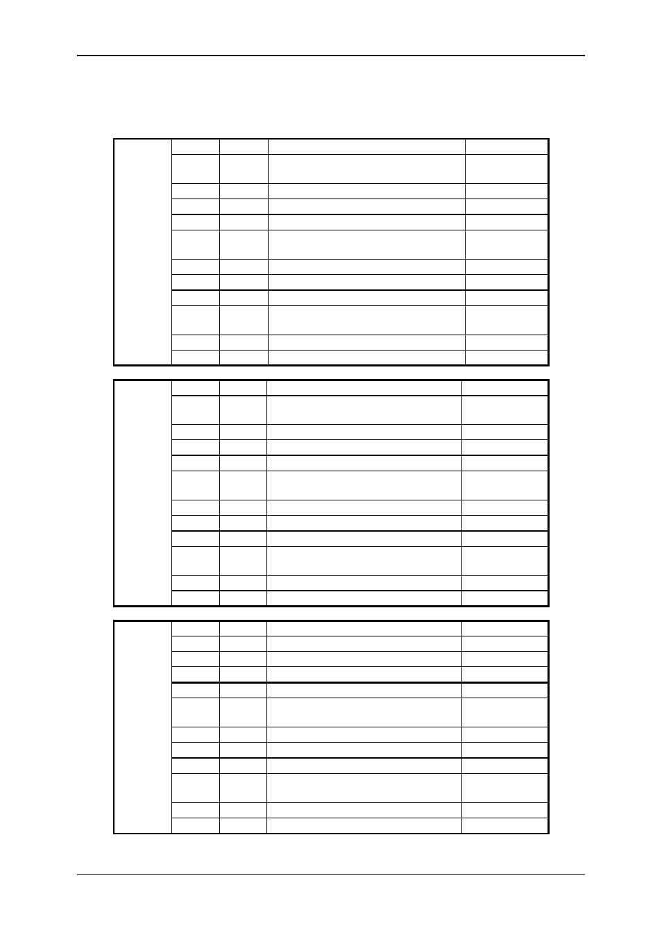
3.3 Terminal Allocations
Plugs Pin
Channel
Function
I/O
1
K
Analog input K
IN
2
C
HSI Channel C /
Sensor recognition input K
IN / OUT
3
GND
4
Power supply
5
J
Analog input J
IN
6
B
HSI Channel B /
Sensor recognition input J
IN / OUT
7
GND
8
Power supply
9
I
Analog input I
IN
10
A
HSI Channel A /
Sensor recognition input I
IN / OUT
11
GND
X1
12
Power supply
1
N
Analog input N
IN
2
F
HSI Channel F /
Sensor recognition input N
IN / OUT
3
GND
4
Power supply
5
M
Analog input M
IN
6
E
HSI Channel E /
Sensor recognition input M
IN / OUT
7
GND
8
Power supply
9
L
Analog input L
IN
10
D
HSI Channel D /
Sensor recognition input L
IN / OUT
11
GND
X2
12
Power supply
1
L
+/-10V, Channel L
IN
2
GND +/-10V
3
P
+/-10V, Channel P
IN
4
GND +/-10V
5
P
Analog input P
IN
6
H
HSI Channel H /
Sensor recognition input P
IN / OUT
7
GND
8
Power supply
9
O
Analog input O
IN
10
G
HSI Channel G /
Sensor recognition input O
IN / OUT
11
GND
X3
12
Power supply