3 setup and function, 1 hardware setup, 2 control elements/connections – HYDAC CMU 1000 User Manual
Page 13
Condition Monitoring Unit CMU 1000
Page 13
Revised 17.12.2009
HYDAC ELECTRONIC GMBH Mat.-No.:
669749
3 Setup and Function
The CMU1000 is an electronic device for regular (permanent) status monitoring of
hydraulic systems or machinery.
This procedure is also referred to as "Condition Monitoring".
3.1 Hardware Setup
In order to fulfill the aforementioned task, the CMU 1000 must be supplied with relevant
machinery and/or systems data, which it receives through connected sensors. The
recorded data (whether processed or unprocessed) can be forwarded by the CMU
1000 through various interfaces to other units.
The CMU 1000 is equipped with a background-lit LCD display as well as three
different-colored LEDs for the status display and presentation of messages and values.
The entering of data and commands can proceed directly at the device by means of a
keypad,
within the specified menu structure, among other ways.
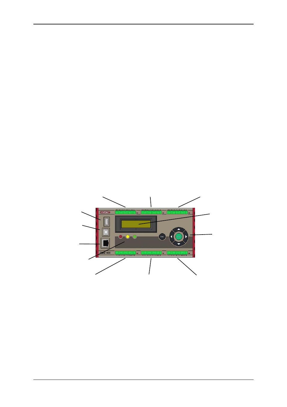
3.2 Control Elements/Connections
X1
X2
X3
HSI-channel A, B, C
HSI-channel D, E, F
HSI-channel G, H
Analog IN I, J, K
Analog IN L, M, N
Analog IN O, P and ± 10V L, P
with power supply
with power supply
with power supply
USB Master
(for MSD)
LCD display
USB Slave
(PC connection)
Keypad
Ethernet
Status LEDs
X4
X5
X6
CAN, Frequency IN Q, R, Power supply. 24V 4x Relay OUT
Digital IN, Analog OUT RS232, HSI-Master, (changer)
IO-Link