EUCHNER AS-i Safety Monitor for 2 AS-i circuits User Manual
Page 86
86
Subject to reasonable modifications due to technical advances
Id.-No.: 103336
Issue date - 24.10.2008
EUCHNER GmbH + Co. KG
Kohlhammerstraße 16 • D-70771 Leinfelden-Echterdingen
Tel. +49/711/75 97-0 • Fax. +49/711/753316
AS-i Safety Monitor for 2 AS-i circuits
Diagnostics for AS-i Monitor and networking using AS-i Master
11.4.3.3
Vendor Specific Object 8 - Device Colors OSSD 1 with component index
association
Read only.
This object contains all the devices associated with Release Circuit 2, the colors
as well as additional information for all release circuits with the component index
association for the configuration.
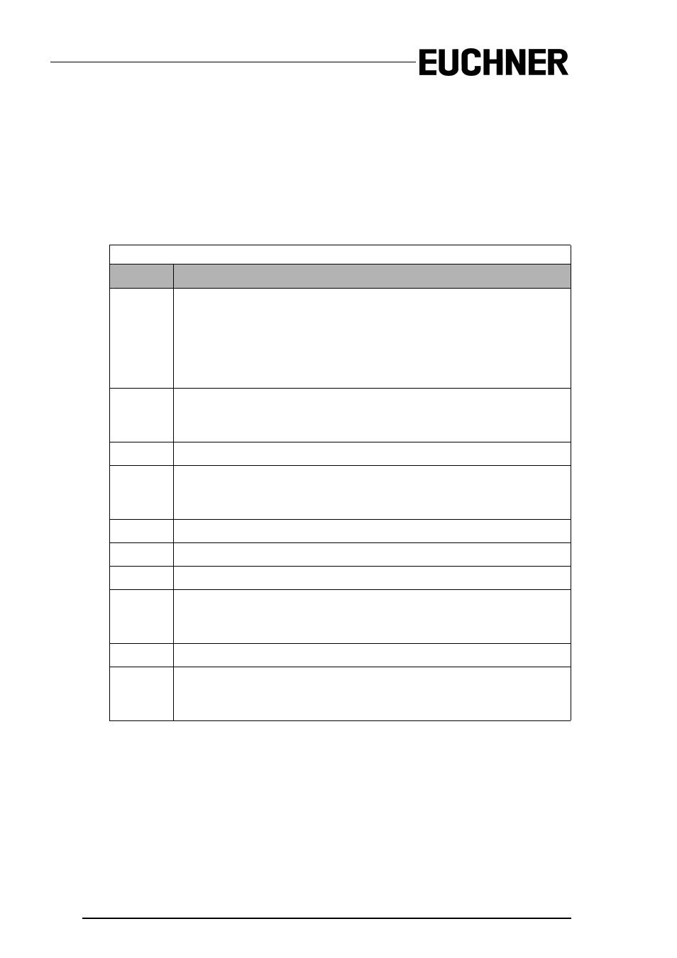
Coding for the states and colors
Byte
Meaning
1
Bit 0 0=Configuration mode, 1=protecting mode
Bit 3 ... 1 reserved, 0
Bit 4 status 1.Y1, EDM1 (0=open)
Bit 5 status 1.Y2, Start1 (0=open)
Bit 6 status 2.Y1, EDM2 (0=open)
Bit 7 status 2.Y2, Start2 (0=open)
2
Relay status, Output 1+2
Bit 3 ... 0 State Output 1, diag_pc.ossd[0].relay-state
Bit 7 ... 4 State Output 2, diag_pc.ossd[1].relay-state
3 ... 8
...
9
Relay status, Output 15+16
Bit 3..0 State Output 15, diag_pc.ossd[14].relay-state
Bit 7..4 State Output 16, diag_pc.ossd[15].relay-state
10
Bit field for devices which are present. Device 7..0
11 ... 40
...
41
Bit field for devices which are present. Device 248..255
42
Color - Device 1+2
Bit 3 ... 0 Color Device 1, diag_pc.device[0].color
Bit 7 ... 4 Color Device 2, diag_pc.device[1].color
43 ... 168
...
169
Device 255+256
Bit 3 ... 0 Color Device 255, diag_pc.device[254].color
Bit 7 ... 4 Color Device 256, diag_pc.device[255].color
Tab. 11-17.