Enerpac ATP-Series User Manual
Page 7
7
WARNING: Before beginning any maintenance or
repairs, be sure that oil return-to-tank valve is open and
that air-shutoff valve is closed. Always disconnect air
and hydraulic lines from pump. Verify that gauges indicate zero
[0] psi/bar.
7.1 Air Filter
Replace the air fi lter element if it appears dirty, or if there is a
noticeable drop in airfl ow. See Figure 9 for parts diagram.
7.2 Filter Bowl Drain Port
The fi lter bowl will automatically drain itself when the water level
rises to approximately 1/3 bowl height. The bowl must be
pressurized to at least 22 psi [1,5 bar] for automatic draining to
occur. If desired, a drain hose with a 1/8 inch BSPP fi tting (user-
supplied) can be connected to the bowl drain port.
Replace the entire bowl assembly if the auto-drain feature fails to
operate. See Figure 9 for parts diagram.
IMPORTANT: To prevent damage to the auto-drain assembly, do
not attempt to loosen the drain port nut. The bowl contains no
manual drain valve. If manual draining is desired, shut-off air
supply and drain any retained water by removing the bowl.
7.3 Air Muffl er
Periodically inspect the air muffl er. Remove any loose dirt or oil
residue with a rag. Replace the muffl er if it becomes clogged or
if there is a noticeable increase in pump noise. See Figure 8 for
location.
7.4 Oil Change
Enerpac HF oil is a crisp blue color. Frequently check oil condition
for contamination by comparing pump oil to new Enerpac oil. As
a general rule, completely drain and clean the reservoir every 250
hours, or more frequently if used in dirty environments.
Change the oil as described in the following steps. Refer to Figure
8:
1. Close reservoir outlet valve.
2. Disconnect
oil
hose
at
hydraulic
fi lter. Place a suitable
container under open end of hose.
3. Open the reservoir outlet valve. Allow oil to drain into the
container below. Dispose of used oil in accordance with all
applicable regulations and laws.
4. Disassemble
the
hydraulic
fi lter assembly. Clean and reinstall
(or replace) the hydraulic fi lter element. Refer to Section 7.5
for additional information.
5. Reattach
oil
hose
to
hydraulic
fi lter. To prevent air entry or
leaks, be sure connections are tight.
6. Open reservoir outlet valve. Prime the pump as described in
Section 4.4.
7.5 Hydraulic Filter
Remove and inspect the hydraulic fi lter element at every oil
change. The element can be cleaned and reused if it is in good
condition. However, a new element should be installed if the old
element is damaged or has been cleaned more than three times.
Check the element if a noticeable drop in pump performance
occurs. See Figure 10 for parts diagram.
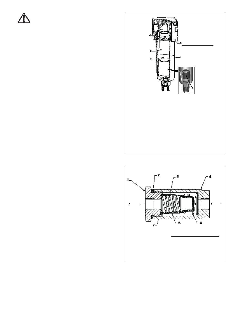
Figure 9, Air Filter Bowl Details
Figure 10, Hydraulic Filter Details
Key:
1. Auto-Drain Bowl Assy. (Camozzi P/N C238-F11/3)
2. Baffl e/Element Assy. (Camozzi P/N 60W3302-0035)
3. Filter Element, 25 Micron (Camozzi P/N 70-3302-0034)
4. O-Ring
5. Housing Assy.
6. Auto-Drain (included with item #1)
Note: For additional
information, go to
www.camozzi.com.
Key:
1. End Cap
2. O-Ring
3. Spring
4. Housing
5. Spring
6. Element, 90 Micron (Arrow P/N EK9052V-90)
7. Gasket
OIL OUT
OIL IN
Note: For additional information,
go to
www.arrowpneumatics.com.