Enerpac ATP-Series User Manual
Page 4
4
4.0 PUMP SET-UP
4.1 Oil Reservoir
Check pump oil level prior to start-up. Before checking oil level:
• Be sure that air-shutoff valve is CLOSED and that oil return-to-
tank valve is OPEN. See Figure 1.
• Be sure that the pump hydraulic pressure and air pressure
gauges both indicate zero [0] psi/bar.
The reservoir is FULL when oil level is at the top of the reservoir
as shown in Figure 3. Oil capacity is approximately 1 US gallon
[3,8 liters]. Use Enerpac Type HF Oil.
IMPORTANT: Add oil only when all system components are fully
retracted, or the system will contain more oil than the reservoir
can hold.
Filler Cap
OIL LEVEL
OPEN
CLOSED
FULL
Reservoir
Outlet
Valve
Figure 3, Hydraulic Oil Reservoir
4.2 Air and Hydraulic Connections
WARNING: Before connecting air supply, ensure that
the air-shutoff (on-off) valve is closed (i.e. handle in
vertical position) and that the oil return-to-tank valve is
open. See Figure 1. Also, be sure that the air pressure regulator
is fully turned off, so that pump air pressure gauge indicates zero
[0] psi.
Make connections as required:
• The pump air inlet is located on the air pressure regulator
assembly. It is a standard 1/2" NPT connection.
• The pump hydraulic oil outlet is a 1/4" female BSPP connection.
On pumps used in bolting applications, a female quick-disconnect
coupler is typically installed in the BSPP connection.
4.3 Air Requirements
Pump air consumption is approximately 21 SCFM [113 l/min] of
free air at 100 psi [6,8 bar] oil discharge pressure. At lower air
pressures and higher hydraulic pressures, air consumption will
be reduced proportionally to the fl ow rates indicated.
IMPORTANT: Pump air supply pressure should not exceed 90
psi [6,2 bar] static.
WARNING: The pump air pressure relief valve is factory
set at approximately 90 psi [6,2 bar]. To prevent personal
injury and equipment damage, do not attempt to raise
relief valve setting.
Use only dry and fi ltered compressed air. Use of a water separator
is strongly recommended.
Pump internal components are self-lubricating. Lubricated air is
NOT required.
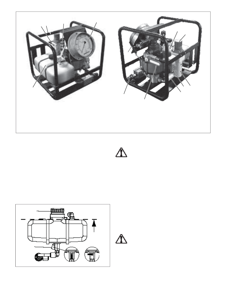
Figure 2, Pump Features and Components (Note: guards and covers removed for illustrative purposes only.)
Key:
1. Air Inlet Connection (1/2 NPT)
2. Roll
Cage
3. Air
Muffl er
4. Hydraulic Pressure Gauge
5. Hydraulic Oil Reservoir
6. Air Pressure Gauge
7. Air Pressure Regulator
8. Filter Bowl Assembly
9. Air Pressure Relief Valve
10. Hydraulic Filter
11. Air-Shutoff Valve
12. Hydraulic Oil Outlet Connection
13. Oil Return-to-Tank Valve
(pressure release to reservoir)
7
8
12
13
11
10
9
6
4
5
2
3
1