Det-Tronics PIRECL Infrared Hydrocarbon Gas Detector PointWatch Eclipse User Manual
Page 63
H-3
95-8526
14.2
settinG netWorK ADDresses
overview of network Addresses
Each PIRECL IR gas detector on the EQP LON must be assigned a unique address. Addresses 1 to 4 are reserved for
the EQP controller. Valid addresses for field devices including PIRECL gas detectors are from 5 to 250.
ImpoRtANt
If the address is set to zero or an address above 250, the system will ignore the switch setting and the device.
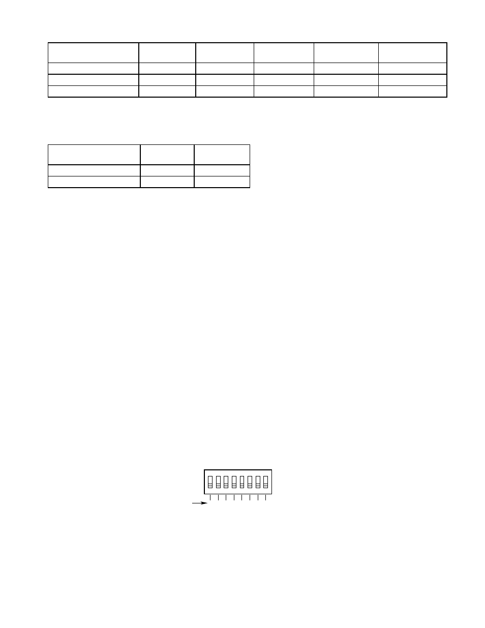
The LON address is programmed by setting rocker switches on an 8 switch “DIP Switch” located within the PIRECL
housing. The address number is binary encoded with each switch having a specific binary value with switch 1 being
the LSB (Least Significant Bit). (See Figure C-1.) The device’s LON address is equal to the added value of all closed
rocker switches. All “Open” switches are ignored.
example
: for node No. 5, close rocker switches 1 and 3 (binary values 1 + 4); for node No. 25, close rocker switches
1, 4 and 5 (binary values 1 + 8 + 16).
NOTE
For convenience in setting LON address switches, a “Rocker Switch Table” is included in the EQP System
manual (form 95-8533).
Table H-4—PIREcL Faults and Fixed Logic System Outputs
1
2
3
4
5
6
7
8
1
2
4
8 16 32 64 128
ON
NODE ADDRESS EQUALS THE ADDED VALUE
OF ALL CLOSED ROCKER SWITCHES
A2190
BINARY
VALUE
CLOSED = ON
OPEN = OFF
Figure H-1—PIREcL Address Switches
Table H-3—PIREcL Fixed Alarm Logic (Thresholds Programmed using S3 configuration Software)
Field Device
Fire
Alarm
high Gas
Alarm
low Gas
Alarm
trouble
supervisory
PIRECL (Point IR Eclipse)
High Alarm
X
Low Alarm
X
Field Device vFD Faults
trouble
leD
trouble
relay
Calibration Fault
X
X
Dirty Optics
X
X