WIKA CPC6000 User Manual
Page 41
Automated Pressure Calibrator
CPC 6000
Mensor/WIKA Operating Instructions - CPC 6000
41
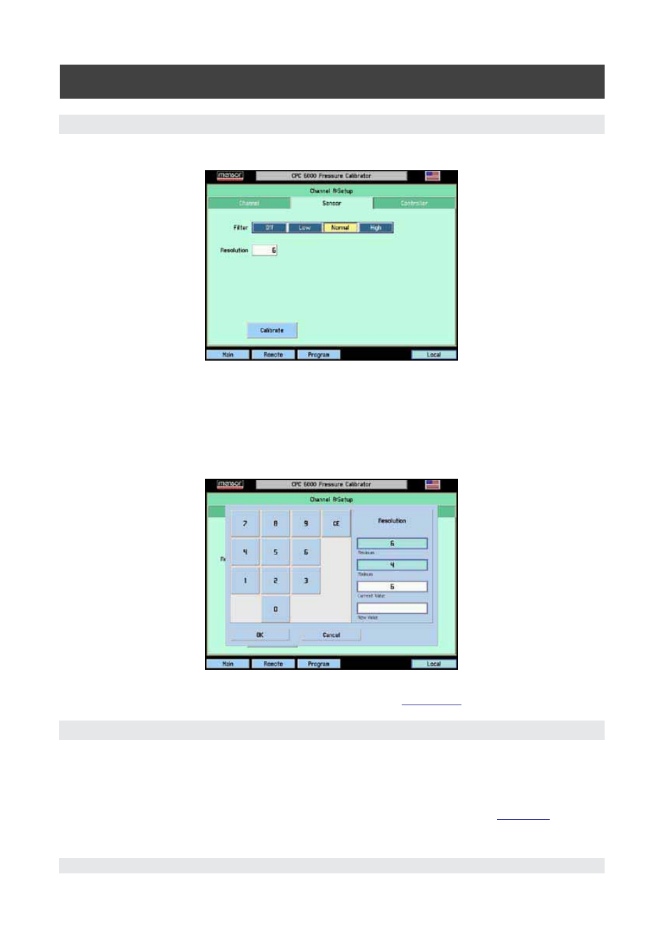
6.6.2 [Sensor] Setup
Touch the [Sensor] tab and Figure 6.6.2A will appear.
Figure 6.6.2A - Sensor Setup Screen
Filter: The Filter is an electronic filter to smooth out the pressure readings. Because of the differences
in resolution, more filtering may display a more stable reading for some pressure units. Select the best
filter for the current units. [Off], [Low], [Normal], [High].
Resolution: The Resolution [value] key allows the user to enter the number of significant digits that will
be displayed on the operate screen. See Figure 6.6.2B.
Figure 6.6.2B - Resolution Window
[Calibrate] Setup key: Details for the [Calibrate] key are given in
Section 10
, Calibration.
6.6.3 [Controller] Setup
The controller setup screen (Figure 6.7.1A for the pump regulator or Figure 6.8 for the solenoid valve
regulator) is used to set the control parameters for the selected pressure control channel.
The controller test screens are an interactive diagnostic display used for troubleshooting the overall
pneumatic system of the CPC 6000. Proper use of these features are described in
Section 9
, Mainte-
nance.