Kramer Electronics VS-3232DN User Manual
Page 11
VS-3232DN - Defining the VS-3232DN 32x32 Digital Matrix Switcher
7
VS
-32
32D
N
–
D
e
fin
in
g
t
h
e
V
S
-3
232
D
N
32
x3
2 D
ig
it
al
M
a
tr
ix S
w
it
ch
er
7
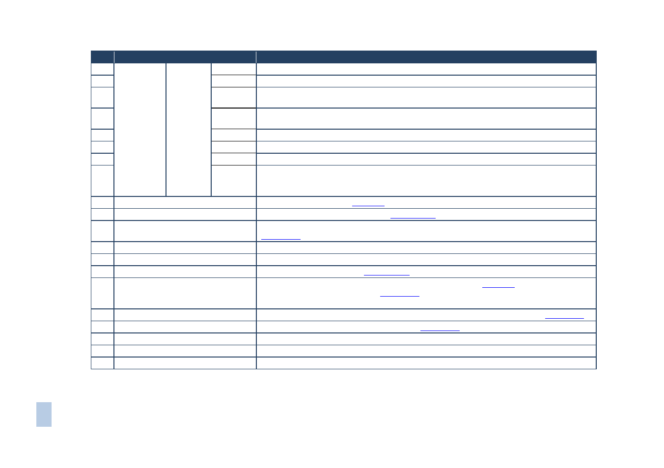
#
Feature
Function
1
Double-
function
Selector
Button
Area
Menu
Button
Functions
ESC
Press to exit the current operation
2
EDID
Press to assign EDID channels
3
STO
Press to store the current setup in the a preset. After pressing the MENU button, this button
lights and is enabled
4
ALL
Press to connect an input to all outputs. After pressing the MENU button, this button lights and
is enabled
5
OFF
Press to turn off an output. After pressing the MENU button, this button lights and is enabled
6
RCL
Press to recall a preset. After pressing the MENU button, this button lights and is enabled
7
DELAY
Press to set the delay between confirming an action and the execution of the action
8
ENT
Press to complete the input-output setup when using a one-digit number instead of two digits.
Press to enter the options in a setup menu. (For example, to enter input 5, you can either press
05 or 5, ENT)
9
BREAKAWAY Button
Press to exit a Menu (see
Section 8
10
DEFAULT SETUP Button
Press to recall the default setup (see
Section 7.4.5
11
OUTPUTS/INPUTS LCD Display
Displays the outputs (upper row) switched to the selected inputs (lower row), (see
Section 7.1
12
). Displays user interface messages and menus
IR Receiver
Infrared remote control sensor
13
IR LED
Lights yellow when receiving commands from the IR remote control transmitter
14
TAKE Button
Press to confirm actions (see
Section 7.3.2
15
MENU Button
Press once to enable the ALL, OFF STO and RCL buttons (see
Section 8
). Press again to
enter the configuration menu (see
Section
When in a Menu, press to cycle through the menu items
16
LOCK Button
Press and hold for approximately 2 sec to lock/unlock the front panel buttons (see
Section 7.5
17
Power Supply
Supplies power to the chassis and cards (see
Section 7.6
18
Power Supply
Supplies power to the device
19
POWER LED
Lights green when the device is powered on
20
ERROR LED
Lights red when there is a fault with the power supply