Nstalling, Eter, Etting – Red Lion PAX2A User Manual
Page 6: Umpers, Rear terminals, Installation, Installation environment, Input range jumpers
6
1.0 i
nsTalling
The
m
eTer
2.0 s
eTTing
The
J
umpers
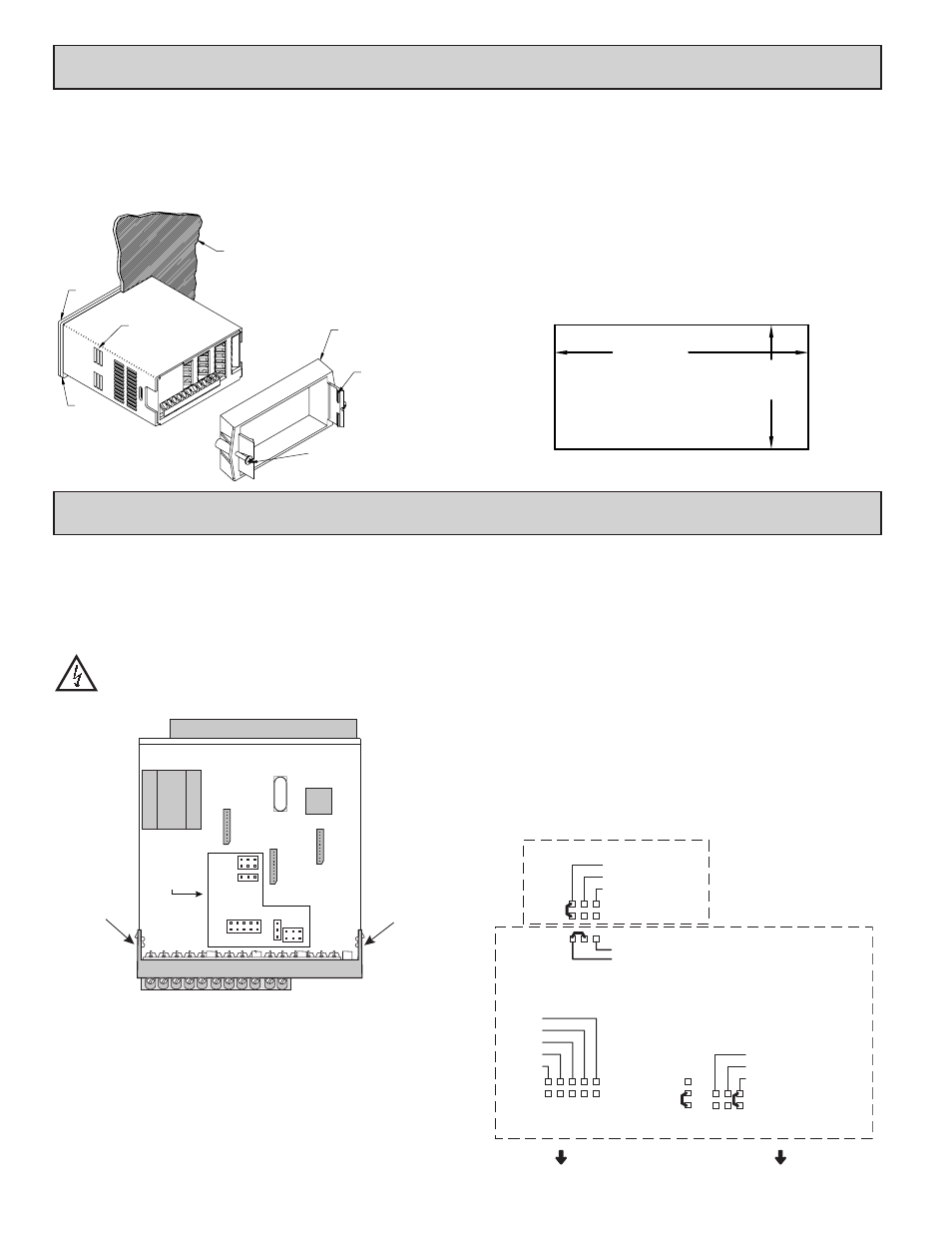
Installation
The PAX2A meets NEMA 4X/IP65 requirements when properly installed.
The unit is intended to be mounted into an enclosed panel. Prepare the panel
cutout to the dimensions shown. Remove the panel latch from the unit. Slide the
panel gasket over the rear of the unit to the back of the bezel. The unit should
be installed fully assembled. Insert the unit into the panel cutout.
While holding the unit in place, push the panel
latch over the rear of the unit so that the tabs of
the panel latch engage in the slots on the
case. The panel latch should be
engaged in the farthest forward slot
possible. To achieve a proper
seal, tighten the latch
screws evenly until the unit is snug in the panel (Torque to approximately 7
in-lbs [79N-cm]). Do not over-tighten the screws.
Installation Environment
The unit should be installed in a location that does not exceed the operating
temperature and provides good air circulation. Placing the unit near devices that
generate excessive heat should be avoided.
The bezel should only be cleaned with a soft cloth and neutral soap product.
Do NOT use solvents. Continuous exposure to direct sunlight may accelerate the
aging process of the bezel.
Do not use tools of any kind (screwdrivers, pens, pencils, etc.) to operate the
keypad of the unit.
PANEL
LATCHING
SLOTS
BEZEL
PANEL
GASKET
PANEL
LATCH
LATCHING
TABS
PANEL
MOUNTING
SCREWS
-.00
(92 )
-.0
+.8
3.62
+.03
(45 )
1.77
-.0
+.5
-.00
+.02
PANEL CUT-OUT
The PAX2A meter has four jumpers that must be checked and/or changed
prior to applying power. The following Jumper Selection Figures show an
enlargement of the jumper area.
To access the jumpers, remove the meter base from the case by firmly
squeezing and pulling back on the side rear finger tabs. This should lower the
latch below the case slot (which is located just in front of the finger tabs). It is
recommended to release the latch on one side, then start the other side latch.
Warning: Exposed line voltage exists on the circuit boards. Remove
all power to the meter and load circuits before accessing inside of
the meter.
INPUT RANGE JUMPERS
Voltage Input
Two jumpers are used in configuring the meter for voltage/resistance. The
first jumper, T/V, must be in the V (voltage) position. The second jumper is used
to select the proper voltage input range. (This jumper is also used to select the
current input range.) Select a range that is high enough to accommodate the
maximum signal input to avoid overloads. For proper operation, the input range
selected in programming must match the jumper setting.
Current Input
For current input, only one jumper must be configured to select the current
range. This jumper is shared with the voltage input range. To avoid overloads,
select the jumper position that is high enough to accommodate the maximum
signal input level to be applied.
Note: The position of the T/V jumper does not matter when the meter is in the
current input mode.
Temperature Input
For temperature measurement the T/V jumper must be in the T (temperature)
position. For RTD sensors the RTD jumper must also be set.
Resistance Input
Three jumpers are used to configure the resistance input. The T/V jumper
must be in the V (voltage) position, and the excitation jumper must be in the
1.05 mA REF position. The voltage/resistance jumper position is determined by
the input range.
Excitation Output Jumper
This jumper is used to select the excitation range for the application. If
excitation is not being used, it is not necessary to check or move this jumper.
Main Circuit Board
REAR TERMINALS
FRONT DISPLAY
I
T
V
RTD
JUMPER
LOCATIONS
100
Finger
Tab
Finger
Tab
EXCITATION OUTPUT JUMPER
INPUT RANGE JUMPERS
18V @ 50mA
2V REF.
1.05 mA REF.
10 ohm RTD
100 ohm RTD
RTD INPUTS
CURRENT INPUTS
2 A
.25 A
.025 A
.0025 A
250 µA
TEMPERATURE
VOLTAGE
THERMOCOUPLE/
VOLTAGE
SELECTION
LV - 250mV/2V/100Ω/1KΩ
M - 10V/100V
HV - 25V/200V/10KΩ
VOLTAGE/RESISTANCE
INPUTS
REAR TERMINALS