Serial rlc protocol communications, Sending serial commands and data to the meter, Command chart – Red Lion PAX2A User Manual
Page 28: Command string construction, Register identification chart, Command string examples, Sending numeric data
28
SERIAL RLC PROTOCOL COMMUNICATIONS
RLC Communications requires the Serial Communications Type Parameter
(tYPE) be set to “rLC”.
SENDING SERIAL COMMANDS AND DATA TO THE METER
When sending commands to the meter, a string containing at least one
command character must be constructed. A command string consists of a
command character, a value identifier, numerical data (if writing data to the
meter) followed by a command terminator character * or $.
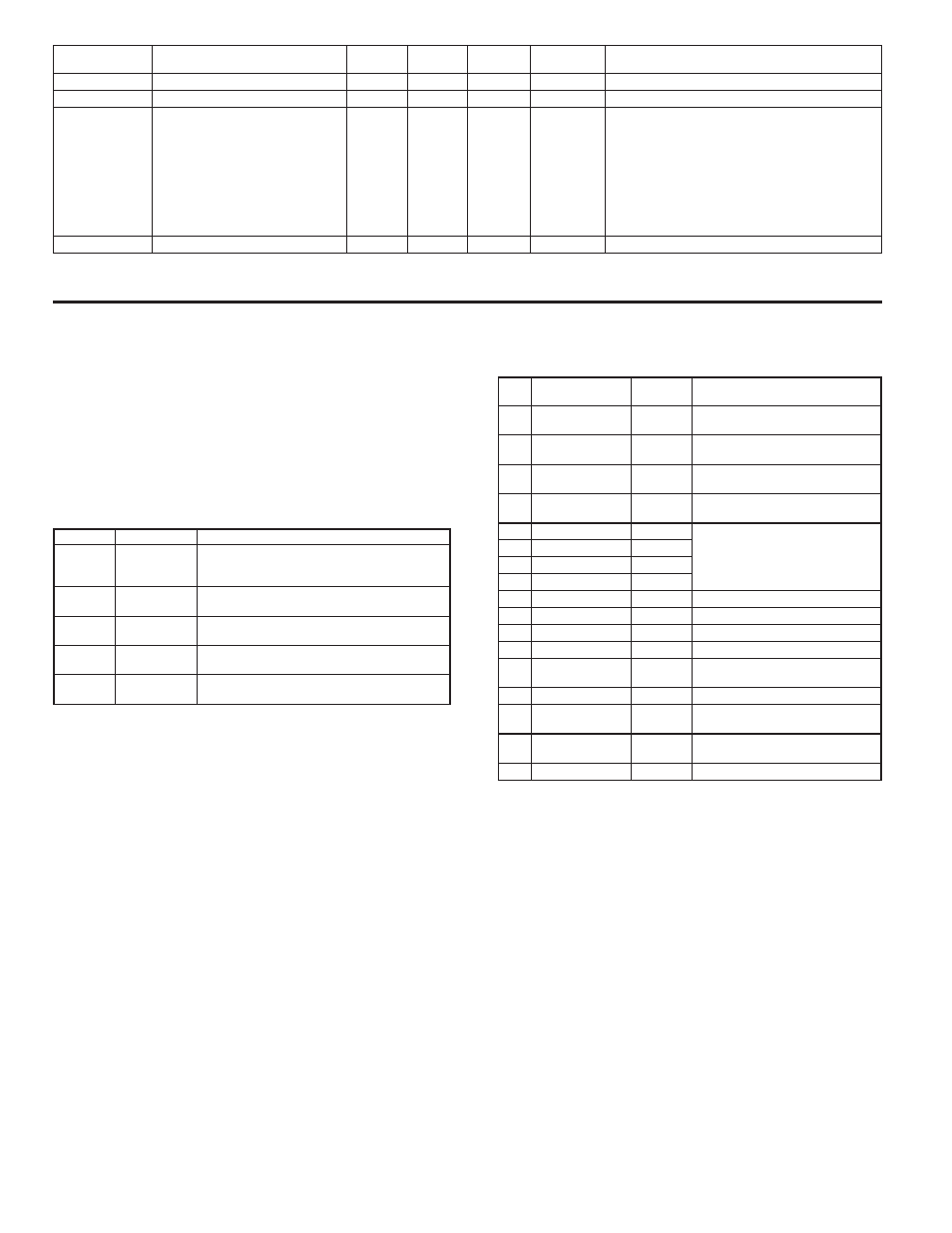
Command Chart
COMMAND DESCRIPTION
NOTES
N
Node Address
Specifier
Address a specific meter. Must be followed by a
one or two digit node address. Not required when
address = 0.
T
Transmit Value
(read)
Read a register from the meter. Must be followed
by register ID character
V
Value Change
(write )
Write to register or output. Must be followed by
register ID character and numeric data.
R
Reset
Reset a register or output. Must be followed by
register ID character.
P
Block Print
Request
Initiates a block print output. Registers are defined
in programming.
Command String Construction
The command string must be constructed in a specific sequence. The meter
does not respond with an error message to invalid commands. The following
procedure details construction of a command string:
1. The first characters consist of the Node Address Specifier (N) followed by a
1 or 2 character address number. The address number of the meter is
programmable. If the node address is 0, this command and the node address
itself may be omitted. This is the only command that may be used in
conjunction with other commands.
2. After the address specifier, the next character is the command character.
3. The next character is the Register ID. This identifies the register that the
command affects. The P command does not require a Register ID character.
It prints according to the selections made in print options.
4. If constructing a value change command (writing data), the numeric data is
sent next.
5. All command strings must be terminated with the string termination
characters * or $. The meter does not begin processing the command string
until this character is received. See Timing Diagram figure for differences
between terminating characters.
Register Identification Chart
ID
VALUE
DESCRIPTION
MNEMONIC APPLICABLE COMMANDS/COMMENTS
A
Input (relative
value)
INP
T, P, R (Reset command resets input
to zero; tares)
B
Total
TOT
T, P, R (Reset command resets total
to zero)
C
Max Input
MAX
T, P, R (Reset command resets Max
to current reading)
D
Min Input
MIN
T, P, R (Reset command resets Min
to current reading)
E
Setpoint 1
SP1
T, P, V, R (Reset command resets
the setpoint output)
F
Setpoint 2
SP2
G
Setpoint 3
SP3
H
Setpoint 4
SP4
I
Band/Deviation 1
BD1
T, V
J
Band/Deviation 2
BD2
T, V
K
Band/Deviation 3
BD3
T, V
L
Band/Deviation 4
BD4
T, V
M
Absolute Input
value
ABS
T
O
Offset
OFS
T, V
U
Auto/Manual
Register
MMR
T, V
W
Analog Output
Register
AOR
T, V
X
Setpoint Register
SOR
T, V
Command String Examples:
1. Node address = 17, Write 350 to Setpoint 1.
String: N17VE350$
2. Node address = 5, Read Input value.
String: N5TA*
3. Node address = 0, Reset Setpoint 4 output.
String: RH*
Sending Numeric Data
Numeric data sent to the meter must be limited to 6 digits (-199999 to
999999). Leading zeros are ignored. Negative numbers must have a minus sign.
The meter ignores any decimal point and conforms the number to the scaled
resolution. (For example: the meter’s scaled decimal point position = 0.0 and 25
is written to a register. The value of the register is now 2.5.
Note: Since the meter does not issue a reply to value change commands, follow
with a transmit value command for readback verification.
REGISTER
ADDRESS
REGISTER NAME
LOW LIMIT HIGH LIMIT
FACTORY
SETTING
ACCESS
COMMENTS
FACTORY SERVICE
40501-40506
Factory Service Registers
N/A
N/A
N/A
Read/Write Factory Use Only - Do Not Modify
41001-41010
Slave ID
N/A
N/A
N/A
Read Only
RLC-PAX2A <0100h><0020h><0020h><0010h
>
= SP Card Status. “0”-No Card, “2”-Dual SP,
“4”-Quad SP
= Linear Card Status. “0”-Not Installled,
“1”-Installed
<0100h> = Version Number (1.00 or higher)
<0020h><0020h> = 32 Register Writes, 32 Register
Reads (Max.)
<0010h> = 16 Register GUID/Scratch
41101-41116
GUID/Scratch
N/A
N/A
N/A
Read/Write Reserved (may be used in future RLC software)