Style, Input, Disply – Red Lion PAX2A User Manual
Page 13: Sclist, User-n, Module 2 - u, Funct ), Usract, User-1, User-2
13
that the 2 scaling points be at opposite ends of the input signal being applied.
The points do not have to be the signal limits. Display scaling will be linear
between and continue past the entered points up to the limits of the Input Signal
Jumper position. Each scaling point has a coordinate-pair of Input Value (INPUt
n
) and an associated desired Display Value (dISPLY n).
Nonlinear - Scaling Points (Greater than 2)
For non-linear processes, up to 16 scaling points may be used to provide a
piece-wise linear approximation. (The greater the number of scaling points used,
the greater the conformity accuracy.) The Input Display will be linear between
scaling points that are sequential in program order. Each scaling point has a
coordinate-pair of Input Value (INPUt n) and an associated desired Display Value
(dISPLY n). Data from tables or equations, or empirical data could be used to
derive the required number of segments and data values for the coordinate pairs.
In the Crimson software, several linearization equations are available.
SCALING STYLE
This parameter does not apply for thermocouple or RTD input ranges.
KEY
key-in data
APPLY
apply signal
If Input Values and corresponding Display Values are known, the Key-in
(KEY) scaling style can be used. This allows scaling without the presence of the
input signal. If Input Values have to be derived from the actual input signal
source or simulator, the Apply (APPLY) scaling style must be used.
INPUT VALUE FOR SCALING POINT 1
-199999
to
999999
For Key-in (KEY), enter the known first Input Value by using the ! or @
arrow keys. (The Input Range selection sets up the decimal location for the Input
Value). For Apply (APPLY), the existing programmed value will appear. If this
is acceptable, press the
P key to save and continue to the next parameter. To
update/program this value, apply the input signal that corresponds to Scaling
Point 1, press @ key and the actual signal value will be displayed. Then press
the
P key to accept this value and continue to the next parameter.
DISPLAY VALUE FOR SCALING POINT 1
-199999
to
999999
Enter the first coordinating Display Value by using the arrow keys. This is the
same for KEY and APPLY scaling styles. The decimal point follows the dECPNt
selection.
INPUT VALUE FOR SCALING POINT 2
-199999
to
999999
For Key-in (KEY), enter the known second Input Value by using the ! or @
arrow keys. For Apply (APPLY), the existing programmed value will appear. If
this is acceptable, press the
P key to save and continue to the next parameter. To
update/program this value, apply the input signal that corresponds to Scaling
Point 2, press @ key and the actual signal value will be displayed. Then press
the
P key to accept this value and continue to the next parameter. (Follow the
same procedure if using more than 2 scaling points.)
DISPLAY VALUE FOR SCALING POINT 2
-199999
to
999999
Enter the second coordinating Display Value by using the ! or @ arrow
keys. This is the same for KEY and APPLY scaling styles. (Follow the same
procedure if using more than 2 scaling points.)
ENABLE SCALE LIST
NO
YES
When enabled, a second list of scaling points is active in the selected
parameter list for List A and List B.
1
3
2
4
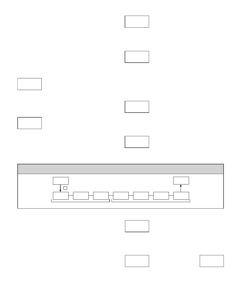
StYLE
KEY
INP
INPUt
0.00
1
dISPLY
0.00
1
INPUt
100.00
2
dISPLY
100.00
2
ScLISt
NO
Pro
NO
Pro
2-FUNCt
P
USrACt
Lo
FNC
USEr-1
NO
FNC
USEr-2
NO
FNC
F1
NO
FNC
F2
NO
FNC
SEC-F1
NO
FNC
SEC-F2
NO
FNC
Function Keys
User Inputs
mOdule 2 - u
ser
i
npuT
/f
unCTiOn
K
ey
p
arameTers
(2-FUNCt)
PARAMETER MENU
The two user inputs are individually programmable to perform specific meter
control functions. While in the Display Mode or Program Mode, the function is
executed the instant the user input transitions to the active state. The front panel
function keys, ! and @, are also individually programmable to perform
specific meter control functions. While in the Display Mode, the primary
function is executed the instant the key is pressed. Holding the function key for
three seconds executes a secondary function. It is possible to program a
secondary function without a primary function.
In most cases, if more than one user input and/or function key is programmed
for the same function, the maintained (level trigger) actions will be performed
while at least one of those user inputs or function keys are activated. The
momentary (edge trigger) actions will be performed every time any of those user
inputs or function keys transition to the active state.
Note: In the following explanations, not all selections are available for both
user inputs and front panel function keys. Displays are shown with each
selection. Those selections showing both displays are available for both. If a
display is not shown, it is not available for that selection. USEr-n will represent
both user inputs. Fn will represent both function keys and second function keys.
USER INPUT ACTIVE STATE
Lo
Hi
Select the desired active state for the User Inputs. Select Lo for sink input,
active low. Select Hi for source input, active high.
NO FUNCTION
No function is performed if activated. This is the factory setting for all user
inputs and function keys.
USrACt
Lo
FNC
USEr-n
NO
FNC
Fn
NO
FNC