Module 6 - s, Setpnt ), Etpoint – Red Lion PAX2A User Manual
Page 20: Utput, Arameters, Select, Action, Assign, Setpnt, Bn-dev
20
Pro
NO
Pro
6-SEtPNt
P
SELECt
NO
SPt
Setpoint
Select
ACtION
NO
Sn
Setpoint
Output
Action
ASSIGN
NONE
Sn
Setpoint
Assignment
SEtPNt
100
Sn
Setpoint
Value
Band/
Deviation
Value
bn-dEV
0
dn
HYStEr
2
Sn
Setpoint
Hysteresis
t-ON
0.0
Sn
On Time
Delay
t-OFF
0.0
Sn
Off Time
Delay
LOGIC
nor
Sn
Output
Logic
rESEt
Auto
Sn
Reset
Action
StndbY
NO
Sn
Setpoint
Standby
Operation
Annun
nor
Sn
Setpoint
Annunciator
Color
NO CHG
Sn
Change
Color
brnAct
OFF
Sn
Probe
Burn-out
Action
mOdule 6 - s
eTpOinT
O
uTpuT
p
arameTers
(6-SEtPNt)
PARAMETER MENU
SETPOINT SELECT
NO
S1
S2
S3
S4
Enter the setpoint (alarm output) to be programmed. The “n” in the following
parameters will reflect the chosen setpoint number. After the chosen setpoint is
completely programmed, the display will return to NO. Repeat step for each
setpoint to be programmed. The NO chosen at SELECt
SPt
, will return to Pro NO. The
number of setpoints available is setpoint output card dependent.
SETPOINT ASSIGNMENT
NONE
rEL
AbS
totAL
Selects the meter value to be used to trigger the Setpoint Alarm. The rEL
setting will cause the setpoint to trigger off of the relative (net) input value. The
relative input value is the absolute input value that includes the Display Offset
Value. The AbS setting will cause the setpoint to trigger off of the absolute (gross)
input value. The absolute input value is based on Module 1 dISPLY and INPUt
entries.
SETPOINT ACTION
NO
Ab-HI
Ab-LO
AU-HI
AU-LO
dE-HI
dE-LO
bANd
bNdIn
totLo
totHI
Enter the action for the selected setpoint (alarm output). See Setpoint Alarm
Figures for a visual detail of each action. The Setpoint Actions that pertains to
the total is only active when the Setpoint Assignment is set to totAL.
NO
= No Setpoint Action
Ab-HI
= Absolute high, with balanced hysteresis
Ab-LO
= Absolute low, with balanced hysteresis
AU-HI
= Absolute high, with unbalanced hysteresis
AU-LO
= Absolute low, with unbalanced hysteresis
dE-HI
= deviation high, with unbalanced hysteresis
dE-LO
= deviation low, with unbalanced hysteresis
bANd
= Outside band, with unbalanced hysteresis
bNdIn
= Inside band, with unbalanced hysteresis
totLo
= Lower 6 digits of 9 digit Totalizer, with unbalanced hysteresis
totHI
= Upper 6 digits of 9 digit Totalizer, with unbalanced hysteresis
SELECt
NO
SPt
ASSIGN
NONE
Sn
ACtION
NO
Sn
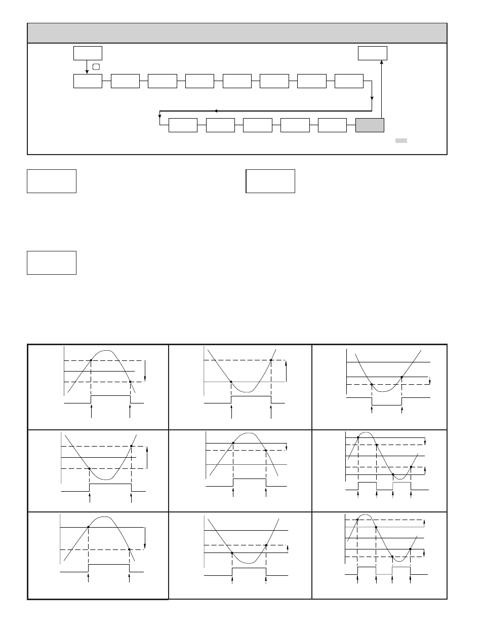
Setpoint Alarm Figures
With reverse output logic
rEv
, the below alarm states are opposite.
ALARM
STATE
OFF
ON
Hys
SP + Hys
SP
OFF
TRIGGER POINTS
ALARM
STATE
OFF
ON
Hys
SP - Bnd
SP
OFF
SP + Bnd
ON
OFF
Hys
TRIGGER POINTS
Absolute Low Acting (Unbalanced Hys) =
AU-LO
Band Outside Acting =
bANd
ALARM
STATE
OFF
ON
Hys
SP + ½Hys
SP
SP - ½Hys
OFF
TRIGGER POINTS
ALARM
STATE
OFF
ON
Hys
SP + Dev
SP
OFF
TRIGGER POINTS
ALARM
STATE
ON
OFF
Hys
SP - Bnd
SP
ON
SP + Bnd
OFF
ON
Hys
TRIGGER POINTS
Absolute Low Acting (Balanced Hys) =
Ab-LO
Deviation High Acting (Dev
> 0) =
dE-HI
Band Inside Acting =
bNdIn
ALARM
STATE
OFF
ON
Hys
SP
SP - Hys
OFF
TRIGGER POINTS
ALARM
STATE
OFF
ON
Hys
SP - Dev
SP
OFF
TRIGGER POINTS
ALARM
STATE
ON
OFF
Hys
SP + (-Dev)
SP
ON
TRIGGER POINTS
Absolute High Acting (Unbalanced Hys) =
AU-HI
This is also for Totalizer alarms:
totLo
,
totHI
Deviation Low Acting (Dev > 0) =
dE-LO
Deviation High Acting (Dev
< 0) =
dE-HI
ALARM
STATE
OFF
ON
Hys
SP + ½Hys
SP
SP - ½Hys
OFF
TRIGGER POINTS
Absolute High Acting (Balanced Hys) =
Ab-HI
Programming information contained in this
manual supercedes all programming information
included with the PAXCDS card.
Temperature
Input Only