Setpnt, Bn-dev, Hyster – Red Lion PAX2A User Manual
Page 21: T-on, T-off, Logic, Reset, Stndby, Annun, Color
21
SETPOINT VALUE
-199999
to
999999
Enter desired setpoint alarm value. Setpoint values can also be entered in the
Display Mode during Program Lockout when the setpoint is programmed as
ENt
in Parameter Module 3. The decimal point position is determined by the
Setpoint Assignment value.
BAND/DEVIATION VALUE
-199999
to
999999
This parameter is only available in band and deviation setpoint actions. Enter
desired setpoint band or deviation value. When the Setpoint Action is
programmed for Band, this value can only be a positive value.
HYSTERESIS VALUE
1
to
65000
Enter desired hysteresis value. See Setpoint Alarm Figures for visual
explanation of how setpoint alarm actions (balanced and unbalanced) are
affected by the hysteresis. When the setpoint is a control output, usually balanced
hysteresis is used. For alarm applications, usually unbalanced hysteresis is used.
For unbalanced hysteresis modes, the hysteresis functions on the low side for
high acting setpoints and functions on the high side for low acting setpoints.
Note: Hysteresis eliminates output chatter at the switch point, while time delay
can be used to prevent false triggering during process transient events.
ON TIME DELAY
0.0
to
3275.0
seconds
Enter the time value in seconds that the alarm is delayed from turning on after
the trigger point is reached. A value of 0.0 allows the meter to update the alarm
status per the response time listed in the Specifications. When the output logic
is rEv, this becomes off time delay. Any time accumulated at power-off resets
during power-up.
OFF TIME DELAY
0.0
to
3275.0
seconds
Enter the time value in seconds that the alarm is delayed from turning off after
the trigger point is reached. A value of 0.0 allows the meter to update the alarm
status per the response time listed in the Specifications. When the output logic
is rEv, this becomes on time delay. Any time accumulated at power-off resets
during power-up.
OUTPUT LOGIC
nor rEv
Enter the output logic of the alarm output. The nor logic leaves the output
operation as normal. The rEv logic reverses the output logic. In rEv, the alarm
states in the Setpoint Alarm Figures are reversed.
RESET ACTION
Auto
LAtCh1s
LAtCh2
Enter the reset action of the alarm output.
Auto
= Automatic action; This action allows the alarm output to automatically
reset off at the trigger points per the Setpoint Action shown in Setpoint Alarm
Figures. The “on” alarm may be manually reset (off) immediately by a front
panel function key or user input.The alarm remains reset off until the trigger
point is crossed again.
LAtCh1
= Latch with immediate reset action; This action latches the alarm
output on at the trigger point per the Setpoint Action shown in Setpoint Alarm
Figures. Latch means that the alarm output can only be turned off by front
panel function key or user input manual reset, serial reset command or meter
power cycle. When the user input or function key is activated (momentary or
maintained), the corresponding “on” alarm output is reset immediately and
remains off until the trigger point is crossed again. (Previously latched alarms
will be off if power up Display Value is lower than setpoint value.)
LAtCh2
= Latch with delay reset action; This action latches the alarm output on
at the trigger point per the Setpoint Action shown in Setpoint Alarm Figures.
Latch means that the alarm output can only be turned off by front panel
function key or user input manual reset, serial reset command or meter power
cycle. When the user input or function key is activated (momentary or
maintained), the meter delays the event until the corresponding “on” alarm
output crosses the trigger off point. (Previously latched alarms are off if
power up Display Value is lower than setpoint value. During a power cycle,
the meter erases a previous Latch 2 reset if it is not activated at power up.)
SETPOINT STANDBY OPERATION
NO YES
When YES, the alarm is disabled (after a power up) until the trigger point is
crossed. Once the alarm is on, the alarm operates normally per the Setpoint
Action and Reset Mode.
SETPOINT ANNUNCIATOR
nor
rEv
FLASh
OFF
The OFF mode disables display setpoint annunciators. The nor mode
displays the corresponding setpoint annunciators of “on” alarm outputs. The
rEv
mode displays the corresponding setpoint annunciators of “off” alarms
outputs. The FLASh mode flashes the corresponding setpoint annunciators of
“on” alarm outputs.
LINE 1 CHANGE COLOR
NO CHG
GrEEN
OrANGE
rEd
GrnOrG
rEdOrG
rEdGrn
LINE 1
This parameter allows the Line 1 Display to change color, or alternate
between two colors, when the alarm is activated. When multiple alarms are
programmed to change color, the highest numbered active alarm (S4-S1)
determines the display color.
The NO CHG selection will maintain the color displayed prior to the alarm
activation. The LINE 1 selection sets the display to the Line 1 Display Color
(Color), programmed in Module 3.
The following programming step is only available when Input Range in Module 1
is set for a temperature input (TC/RTD).
PROBE BURN-OUT ACTION
OFF ON
Enter the probe burn-out action. In the event of a temperature probe failure
(TC open; RTD open or short), the output can be programmed to be on or off.
SEtPNt
100
Sn
bn-dEV
0
dn
HYStEr
2
Sn
t-ON
0.0
Sn
t-OFF
0.0
Sn
LOGIC
nor
Sn
rESEt
Auto
Sn
StndbY
NO
Sn
Annun
nor
Sn
Color
NO CHG
Sn
brnAct
OFF
Sn
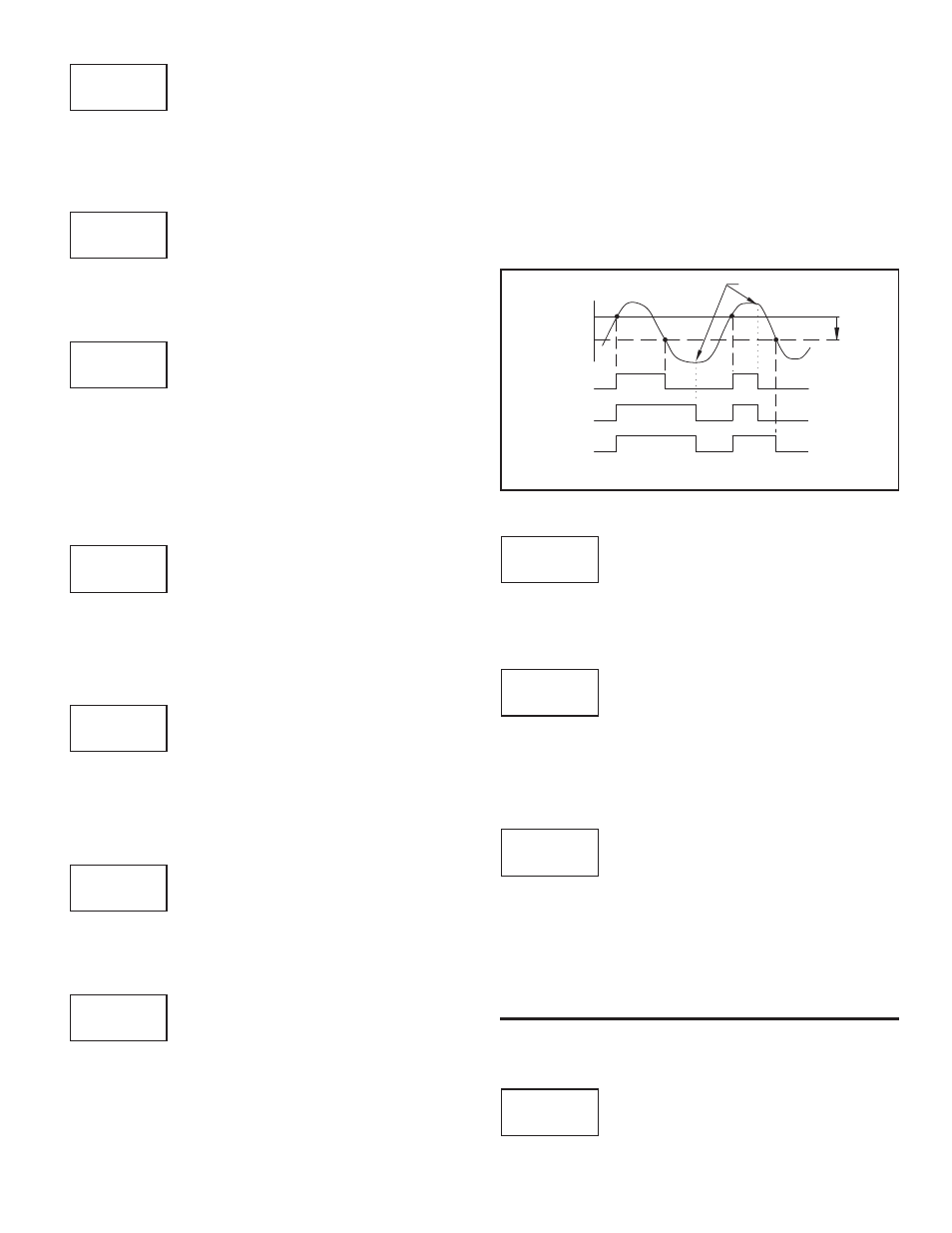
ALARM
STATE
OFF
ON
Hys
SP
OFF
ON
OFF
OFF
ON
OFF ON
OFF
OFF
ON
OFF
ON
OFF
MANUAL
RESET
SP - Hys
( Auto)
(LAtC1)
(LAtC2)
м
н
о
Setpoint Alarm Reset Actions