4 profibus, 1 features, 2 connection – NORD Drivesystems BU0135 User Manual
Page 56
SK 105E…175E Motor Starter Manual
56
Pre-series version
BU 0135 GB-2713
4.4 PROFIBUS
PROFIBUS DP allows the exchange of data between a wide range of automation devices. PLC's, PC's,
operating and monitoring devices can all communicate via a uniform bus in serial bit mode. PROFIBUS DP
is primarily used for communication between sensor and actuator where system response needs to be very
fast. PROFIBUS is used where the time for rapid and complex communication between the individual
devices is critical. PROFIBUS DP is a suitable alternative to expensive 24-volt parallel signal transmission
and transmission of measured values. This type of PROFIBUS, which is optimised to speed, is used for
instance for operating frequency inverters on automation devices.
PROFIBUS communication is specified in the international standards IEC 61158 and IEC 61784. Application
and planning aspects are specified and documented in the guidelines of the PROFIBUS users´ organisation
(PNO). This ensures intercommunication between devices from different manufacturers. Data exchange is
specified in DIN 19245 Part 1 and 2 and application-specific upgrades in Part 3 of this standard. Within the
European field bus standardisation process, PROFIBUS is integrated into the European field bus standard
EN 50170.
4.4.1
Features
· Electrically isolated bus interface
· Baud rate up to 12Mbit/s
· Connection via M12 or terminal possible
· Status display with one LED
· Supports Sync and Freeze modes
· Watchdog function, in case of malfunction all bits of the setpoint PDO are set to 0
· Address setting via rotary coding switch
· The PROFIBUS termination resistor can be switched in via jumpers
· Transfer of 4 control bits and 4 status bits
· no parameter communication
·
4.4.2
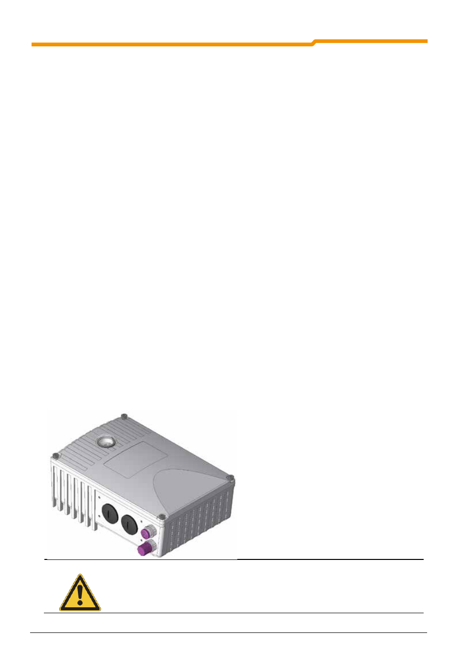
Connection
Connection of the motor starter to the PROFIBUS is made via two M12 sockets. The pin connections of the
sockets correspond to the PROFIBUS standard and can be obtained from the section "Plug connectors for
control connection".
As an alternative, the connection can also be made
directly via terminal X4.
· Pin 83 = PBRA
· Pin 82 = PBRB
NOTE
In case of direct connection to the terminals, there must not be any spur cables,
i.e. the incoming and outgoing cables must be connected to the terminals
together!