Connector & wiring diagram, 4 connector & wiring diagram – FUTEK IHH500 Series User Manual
Page 9
EM1001-B
- 9 -
10 Thomas, Irvine, CA 92618 USA
Tel: (949) 465-0900
Fax: (949) 465-0905
Toll Free: (800) 23 FUTEK
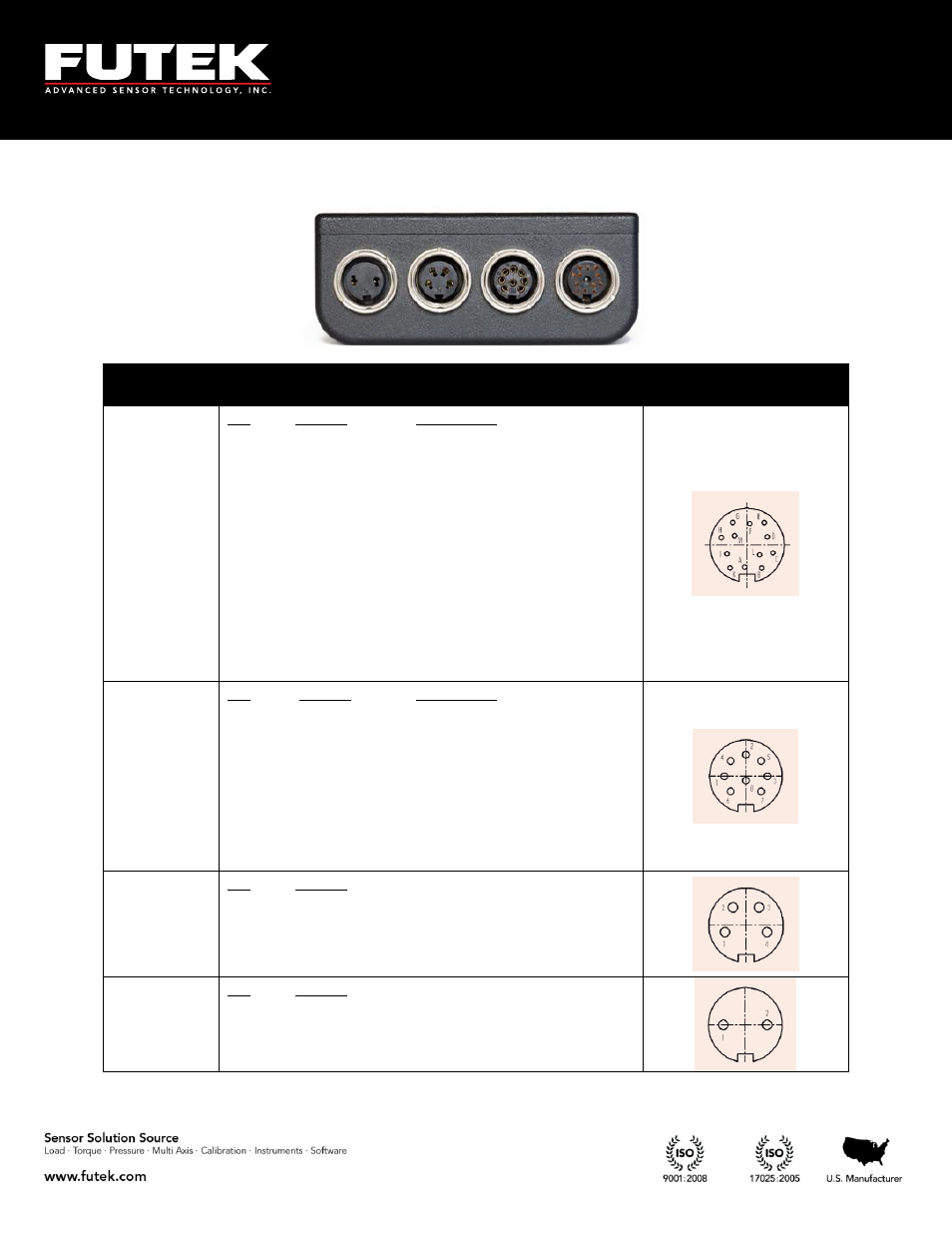
4 Connector & Wiring Diagram
Connectors
Description
Diagram
(Female Insert)
Sensor
Connections
Pin
A
B
C
D
E
F
G
H
J
K
L
M
Symbol
+E
+S
-E
-S
TEDS_IO
24_OUT
GND_OUT
5_OUT
-V
+V
PLEAD
PLAG
Description
+Excitation
+Signal
-Excitation, TEDS return
-Signal
TEDS Data
24V output
Ground
5V Output
-V from sensor
+V from sensor
Leading Pulse from sensor
Lagging Pulse from sensor
Output
Connections
Pin
1
2
3
4
5
6
7
8
Symbol
IDAC
REFRENCE
+R1
VDAC
+R2
GND
-R1
-R2
Description
analog current output signal
analog voltage output return
solid state relay1 (positive)
analog voltage output signal
solid state relay2 (positive)
analog current output return
solid state relay1 (negative)
solid state relay2 (negative)
USB port
Connections
Pin
1
2
3
4
Symbol
VBUS
-D
+D
GND
Power
Connections
Pin
1
2
Symbol
12V
Ground
(Note: These pins are not polarity sensitive)