Tcf12x18s-13, tcf12x20l-13, Chillers turbochill™ air cooled and freecool, Te ch ni ca l fr ee c oo l – Airedale TurboChill FreeCool 200kW - 1830kW User Manual
Page 90: Technical data
90
Chiller Technical Manual 7525355 V1.1.0_04_2013
Chillers
TurboChill™ Air Cooled and FreeCool
Te
ch
ni
ca
l
Fr
ee
C
oo
l
59
60
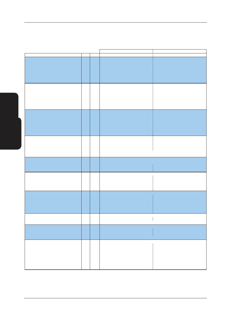
Mechanical Data
Notes Units
TCF12X18L-13
TCF12X20L-13
Cooling Duty - AC Fans
(1)
kW
810
860
Nom Input -Cooling Only
kW
235.9
250.1
EER
(2)
3.43
3.44
ESEER
(3)
4.77
4.77
SEER
(3)
4.61
4.61
Nominal Output - Free Cooling
(4)
kW
686.4
752.3
Ambient when Free Cooling = 100% Nominal DX
(5)
°C
-0.5
0
Cooling Duty - EC Fans
(1)
kW
810
860
Nom Input -Cooling Only
kW
227.7
241.1
EER
(2)
3.56
3.57
ESEER
(3)
5.52
5.55
SEER
(3)
5.28
5.30
Nominal Output - Free Cooling
(4)
kW
686.4
752.3
Ambient when Free Cooling = 100% Nominal DX
(5)
°C
-0.5
0
Cooling Duty - High Airflow EC Fans
(1)
kW
N/A
N/A
Nom Input -Cooling Only
kW
N/A
N/A
EER
(2)
N/A
N/A
ESEER
(3)
N/A
N/A
SEER
(3)
N/A
N/A
Nominal Output - Free Cooling
(4)
kW
N/A
N/A
Ambient when Free Cooling = 100% Nominal DX
(5)
°C
N/A
N/A
Capacity Steps
(6)
%
15-100%
15-100%
Dimensions (H x W x L)
mm
2785 x 2200 x 10550
2785 x 2200 x 11682
Machine Weight
(7)
kg
10745
11630
Operating Weight
(7)
kg
12210
13210
Construction Material
Base: Plain Galvanised Steel, Panels: Galvanised Sheet Steel,
Epoxy Baked Powder Paint, Light Grey (RAL 7035)
Evaporator - Type
Flooded - Shell and Tube Evaporator
Insulation
Class O, UV stable Insulation
Total Max. Water Flow
l/s
74.2
74.2
Total Min. Water Flow
l/s
24.7
24.7
Condenser - Type
Epoxy Coated Aluminium Microchannel & Aluminium Fins
Face Area Total
m²
42.6
47.4
Maximum Airflow - AC Fans
m³/s
70.0
77.7
Maximum Airflow - EC Fans
m³/s
70.0
77.7
Maximum Airflow - High Airflow EC Fans
m³/s
N/A
N/A
Condenser Fan & Motor
Sickle Bladed Axial Fan
Quantity
18
20
Diameter
mm
800
800
Maximum Speed - AC Fans
rpm
710
710
Maximum Speed - EC Fans
rpm
715
715
Maximum Speed - High Airflow EC Fans
rpm
N/A
N/A
Compressor - Type
Turbocor - Oil Free Compressor
Quantity
2
2
Capacity Control
Variable Frequency Drive (VFD) for Linear Capacity Modulation
Refrigeration
Single Circuit
Refrigerant Pre-charged
R134a
R134a
Charge (Total) CCT1 + CCT2
kg
430
445
Refrigeration Control
Electronic Expansion Valve (EEV)
Water System
Grooved Type Coupling and Pipe Assembly
Water Inlet / Outlet
DN150
DN150
Water Drain / Bleed - Evap
inch
1/2
1/2
Water Volume
l
1478.2
1478.2
Minimum System Water Volume
(8)
l
3377.5
3494.7
Max System Operating Pressure
Barg
10
10
Flow Rate
l/s
34.1
36.2
Pressure Drop
kPa
99.3
107.6
Technical Data
Mechanical
TCF12X18S-13, TCF12X20L-13
(1) Based on FC units performance at 16/10°C return/supply temperatures, 35°C ambient, 20% ethylene glycol.
(2) EER = DX cooling output / (compressor input power + fan input power)
(3) ESEER / SEER based upon unit operating at 12 / 7 °C return / supply temperature, 35°C ambient.
(4) Nominal Free Cooling output at 16/10°C return/supply temperatures, 2°C ambient, 20% ethylene glycol.
(5) Ambient temperature that maximum nominal DX duty can be achieved using Free Cooling only.
(6) This is a nominal figure based on full compressor duty, actual turndown depends on both condensing and evaporating temperatures.
(7) Based on standard unit without options, machine weight includes refrigerant charge, operating weight includes refrigerant charge and water volume.
For unit weights with waterside options fitted please contact Airedale.
(8) For minimum system water volume calculation, refer to Design Features & Information - Minimum System Water Volume Calculations.