Design features & information, Pipework design, Refrigeration schematic – Airedale TurboChill FreeCool 200kW - 1830kW User Manual
Page 35: Chillers turbochill™ air cooled and freecool, Introduction
35
Chiller Technical Manual 7525355 V1.1.0_04_2013
Introduction
Chillers
TurboChill™ Air Cooled and FreeCool
Design Features & Information
Pipework Design
Due to the unique oil free operation of the Turbocor compressor, the need for oil entrainment is eliminated. As pipe work
is not required to be sized for oil return it is possible to size pipe work for minimal pressure losses through the system
with maximum cooling capacity and optimised unit EER.
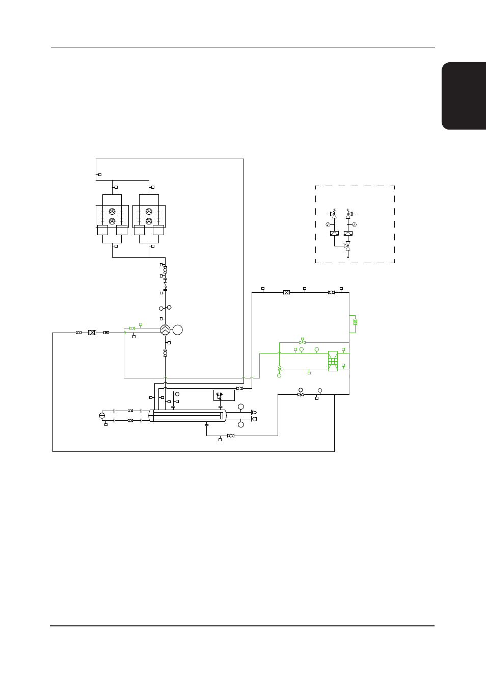
Refrigeration Schematic
Note: Schematic above is for a single circuit machine.
key
1
Turbochill flooded schematic
2
Flooded evaporator
3
Schrader connection
4
Centrifugal compressor
5
Shut off valve
6
Filter drier
7
Sight glass
8
Electronic expansion valve (economiser circuit
only)
9
Condenser section
10
Level transmitter
11
Water connections (Inlet /Outlet)
12
Liquid line
13
Suction line
14
Dual pressure relief valves
15
Liquid level control valve
16
High pressure switch
17
Rotalock adapter
18
Liquid pressure transmitter
19
Solenoid valves
20
Low pressure switch
21
Economiser pressure transducer
22
Temperature sensor
23 Economiser
24
Economiser line
25
Non return valve
26
Liquid level sensor
M
PZH
S
PZH
S
S
S
LT
S
S
PSL
Ti
Ti
M
S
S
S
S
S
S
S
S
S
S
PT
S
S
S
S
S
TCE
S
PT
TT
S
S
S
S
3
3
3
3
3
3
3
3
3
3
3
3
3
3
3
3
3
3
3
3
3
3
3
4
5
5
5
5
5
5
5
5
5
9
9
18
23
6
6
7
17
17
17
17
17
20
8
7
21
2
16
26
19
12
15
14
13
11
24
12
25
24
24
22
1
DUAL PRESSURE RELIEF VALVE
ASSEMBLY WHEN REFRIGERANT CHARGE IS
ABOVE 300KG PER CIRCUIT
PRESSURE
INDICATOR
BURSTING DISC
THREE WAY
VALVE
14