2 voltage test leads and clamp sensor connection – KYORITSU 6305 Instruction Manual User Manual
Page 25
KEW6305
3.4
3.2 Voltage test leads and Clamp sensor connection
Check the followings before connecting the test leads and sensors.
DANGER
● Use only the Voltage test leads supplied with this instrument.
● Use the dedicated Clamp sensor for this instrument, and confirm that the measured current rating of the
Clamp sensor is not exceeded.
● Do not connect all the Voltage test leads or Clamp sensors unless required for measuring the
parameters
desired.
● Connect the test leads and sensors to the instrument first, and only then connect them to the circuit
under
test.
● Never disconnect the Voltage test leads and sensors while the instrument is in use.
WARNING
● Confirm that the instrument is powered off, and then connect the Power cord.
● Connect the Power cord to the instrument first. Cord to be firmly inserted.
● Never attempt to make measurement if any abnormal conditions such as abnormal conditions are
noted, such as a broken Cover and exposed metal parts.
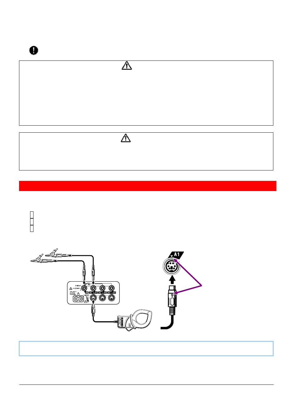
Voltage test leads and Clamp sensor connection
Follow the procedure below, and connect the Voltage test leads and Clamp sensors.
1 Confirm that the instrument is powered off.
2 Connect the appropriate Voltage test leads to the Voltage input terminal on the instrument.
3 Connect the appropriate Clamp sensors to the Current input terminal on the instrument.
Match the direction of the arrow mark indicated on the output terminal of the clamp sensor and
the mark on the Current input terminal on the instrument.
Number of Voltage test leads and Clamp sensors to be used will be different depending on the wiring
configuration under test. For further details, refer to “5.2 Basic Wiring Configuration” in this manual.
Match the arrow marks.