KROHNE IFC 110 Converter User Manual
Page 73
Part C Special applications, functional checks, service, and order numbers Sect. 7.5
05/2003
IFC 110 F
73
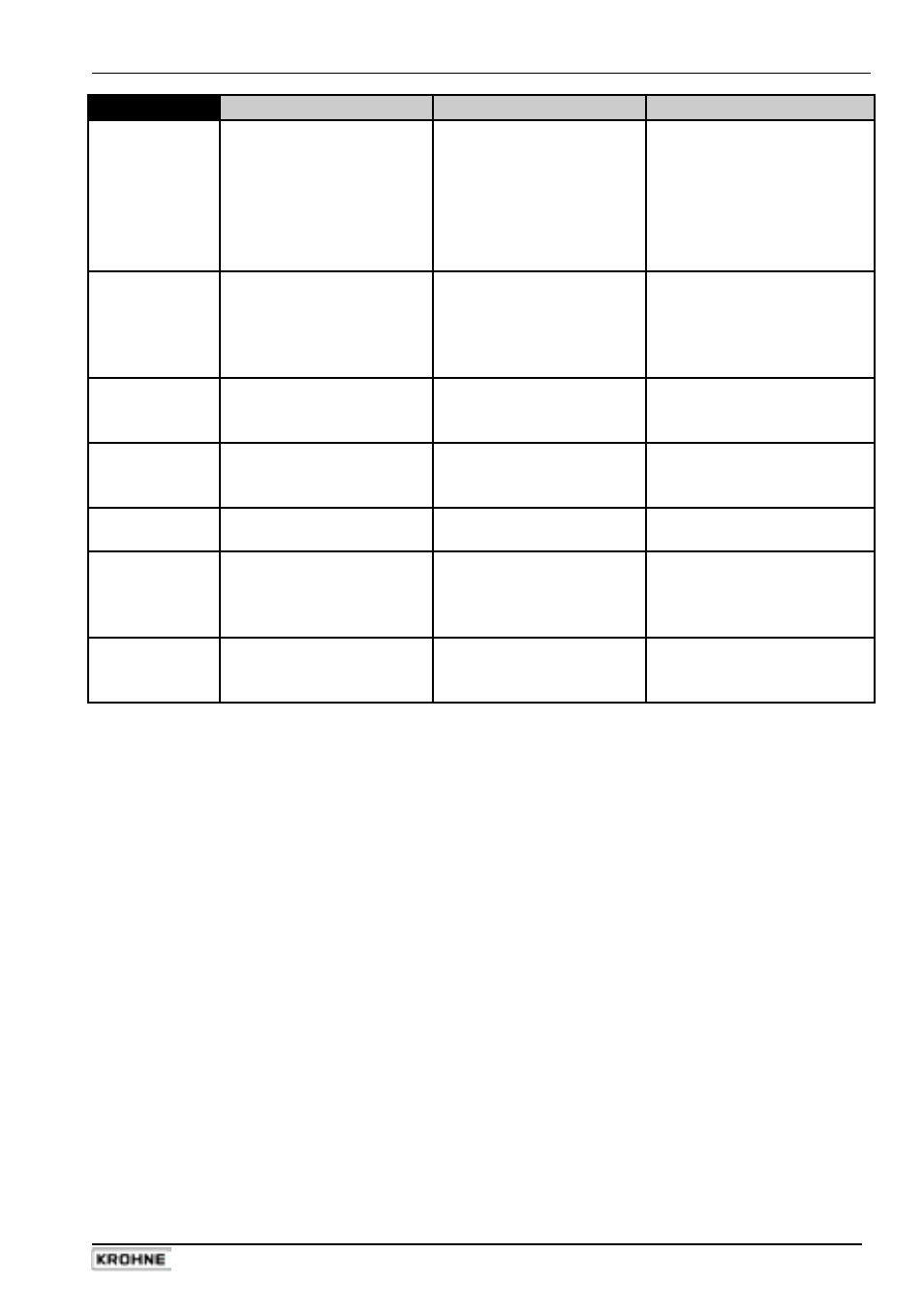
Group I
Faults / Symptoms
Cause
Remedial action
I 3
22 mA are available at
Range of current output I is
Check instrument parameters
current output (fault current)
exceeded
and correct if necessary
(see Sect. 2.2 and 5.7) or con-
sult KROHNE Service, having
first
noted
down
hardware
information and error status,
see Sect. 7.3, Fct. 2.02.
I 4
22 mA are available at
Fatal Error
Replace signal converter or
current output (fault current)
consult KROHNE Service,
and red LED flashes
having first noted down hard-
ware
information
and
error
status, see Sect. 7.3, Fct. 2.02
I 5
Unsteady display
Electric conductivity of
Increase time constant
process liquid too low
(see Sect. 5.2, Fct. 1.2).
Also refer to Sect. 6.7.
I 6
Receiver instruments
Control input C1 or C2 is
Change setting (see Sect. 5.10,
indicate ”constant value”
set to ”Hold outputs” and
Fct. 1.11 and 1.12), or
is activated
deactivate control input.
I 7
Jumping current values
Current output is set to
Change hysteresis or tripping
automatic range change
ranges, see Sect. 5.20.
I 8
F/R-Mode:
Different ranges set for
Change setting,
different displays for identical
”forward flow” and
see Sect. 5.15, Fct. 1.05
flow volumes in both
”reverse flow”
”Rev. range”.
directions
I 9
Receiver instruments
Control input C1 or C2 is set
Change setting (see
indicate ”min. values”
to ”Zero outputs” or ”Hold
Sect. 5.10, Fct. 1.11 and 1.12)
outputs” and is activated
or deactivate control input.