15 f/r mode, forward/reverse flow measurement, 16 output characteristics – KROHNE IFC 110 Converter User Manual
Page 51
Part B IFC 110 F Signal converter Sect. 5.15
05/2003
IFC 110 F
51
5.15 F/R mode, forward/reverse flow measurement
• Refer to Section 2.6 for electrical connection of outputs.
• Define direction of forward flow, see Fct. 3.02, subfunction ”FLOW DIR.”:
in conjunction with F/R operation, this is where to set the direction of the forward flow.
”+” means the same direction as shown by the arrow on the flow sensor.
”-” means the opposite direction.
• Set one of the status outputs to ”SIGN I”, ”SIGN P” or ”SIGN P2”, see Fct. 1.08-1.10 (1.07).
Dynamic behaviour of outputs in case of ”SIGN I, P or P2” see Section 5.8.
• Current and/or pulse outputs must be set to ”2 DIR.”, see Fct. 1.05, 1.06 and 1.07,
subfunctions ”FUNCT. I”, ”FUNCT. P” and ”FUNCT. P2”.
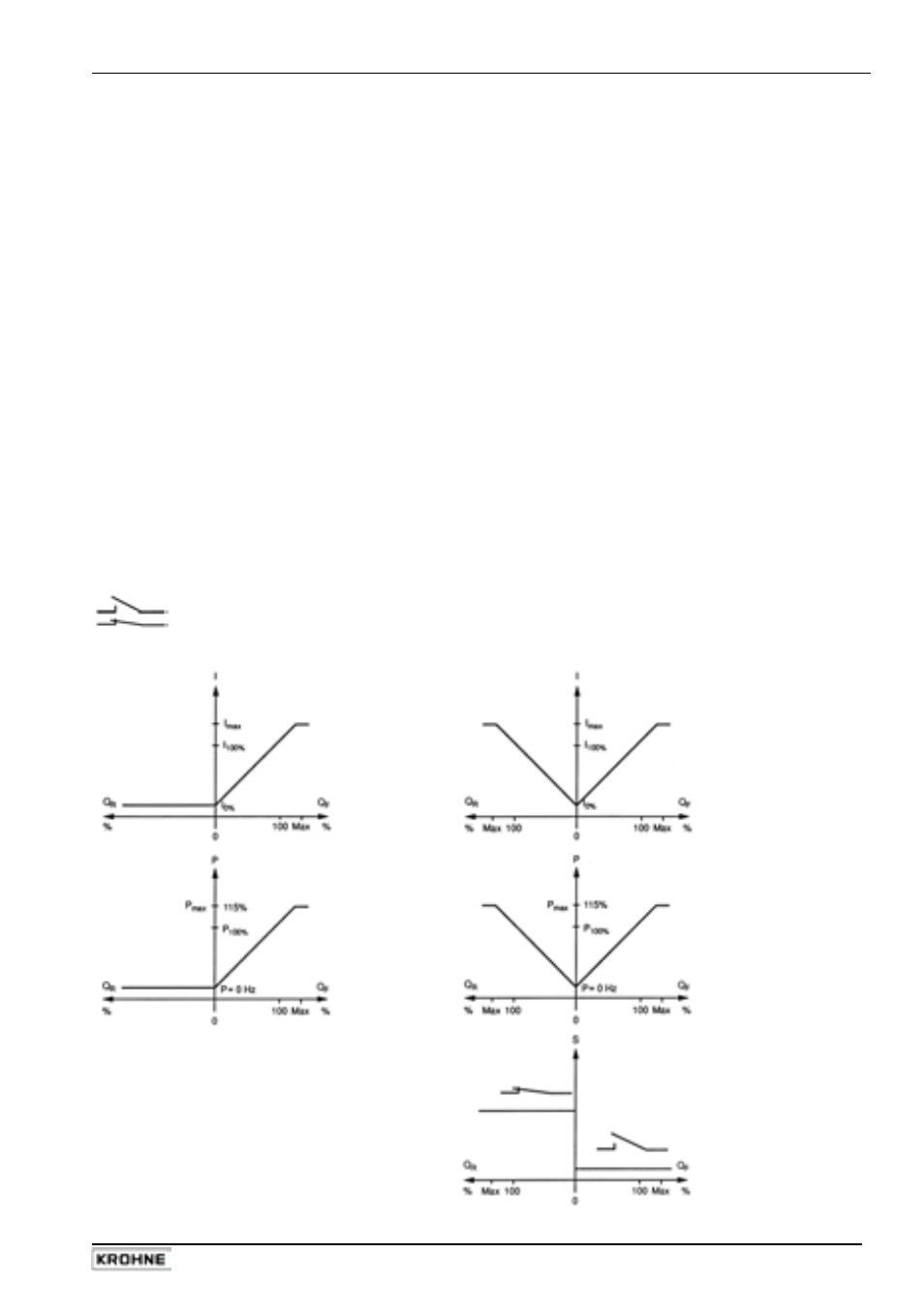
5.16 Output
characteristics
I
current output
I
0%
0 or 4 mA
I
100%
20 mA
P
pulse outputs P and A1 (P2)
P
100%
pulses at Q
100%
, full-scale range
Q
F
1 flow direction, forward flow in F/R mode
Q
R
reverse flow in F/R mode
Q
100%
full-scale range
S
status outputs A1, A2, D1 and D2
switch open
switch closed
1 flow direction
2 flow directions