Install backplate, Front view, End view – Hired-Hand Mega-Cool rev 6-09 User Manual
Page 15
Part No. 4801-5120 Rev. 6-09
Mega-Cool System
Page 15
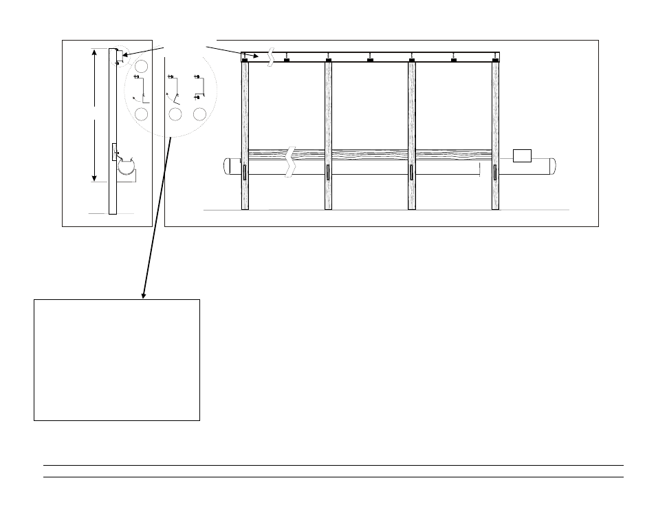
Install BackPlate
1.
Refer to diagram at left. At end post of system on opposite end from float valve, measure dimension
"A" as shown and mark post. See the Framing Diagram on Page 5 and 6 for dimension “A”.
2.
At the other end post of system (end post at float valve side of system) measure dimension "A"
minus one inch (2.5 cm) and mark post. This provides a 1" drop for proper water flow.
NOTE: If a Center-Mount In-Line Pump System is being installed, the BackPlate should be MOUNTED
LEVEL WITHOUT THE 1" DROP.
3.
Stretch chalk line between marks of end posts and mark all posts of system.
4.
For each post of system, align top edge of BackPlate with mark on post. Assemble BackPlate as
shown in diagram at left. Securely mount BackPlate on centers of 4x4" posts, not more than 5 ft.
(1.52 m) O. C. (on center).
5.
Secure BackPlate to wooden framing with #10 x 1" Hex Head screws, or
secure BackPlate to steel framing with #12 x 1" Hex Head TEK screws.
2
1
3
4
Assembly of BackPlate
(1) Install top of BackPlate.
(2) Hook BackPlate Supports in bottom
holes of BackPlate. There are 3
Supports per BackPlate. One on
each end and one in the middle.
(3) Rotate BackPlate Support Brackets
up into position.
(4) Attach with screws.
BackPlate
Front View
“A
End View