In-process operation, 1 mode transition, 2 generation of alarm – Yokogawa EJX930A User Manual
Page 56: 1 indication of alarm, 2 alarms and events, In-process operation -1, Mode transition -1, Generation of alarm -1 7.2.1, Indication of alarm -1, Alarms and events -1
<7. In-Process Operation>
7-1
IM 01C25R03-01E
7. In-Process Operation
This chapter describes the procedure performed
when changing the operation of the function block
of the EJX multivariable transmitter in process.
7.1 Mode Transition
When the function block mode is changed to
Out_Of_Service, the function block pauses and a
block alarm is issued.
When the function block mode is changed to
Manual, the function block suspends updating of
output values. In this case alone, it is possible to
write a value to the OUT parameter of the block
for output. Note that no parameter status can be
changed
7.2 Generation of Alarm
7.2.1 Indication of Alarm
When the self-diagnostics function indicates that a
device is faulty, an alarm (device alarm) is issued
from the resource block. When an error (block
error) is detected in each function block or an error
in the process value (process alarm) is detected, an
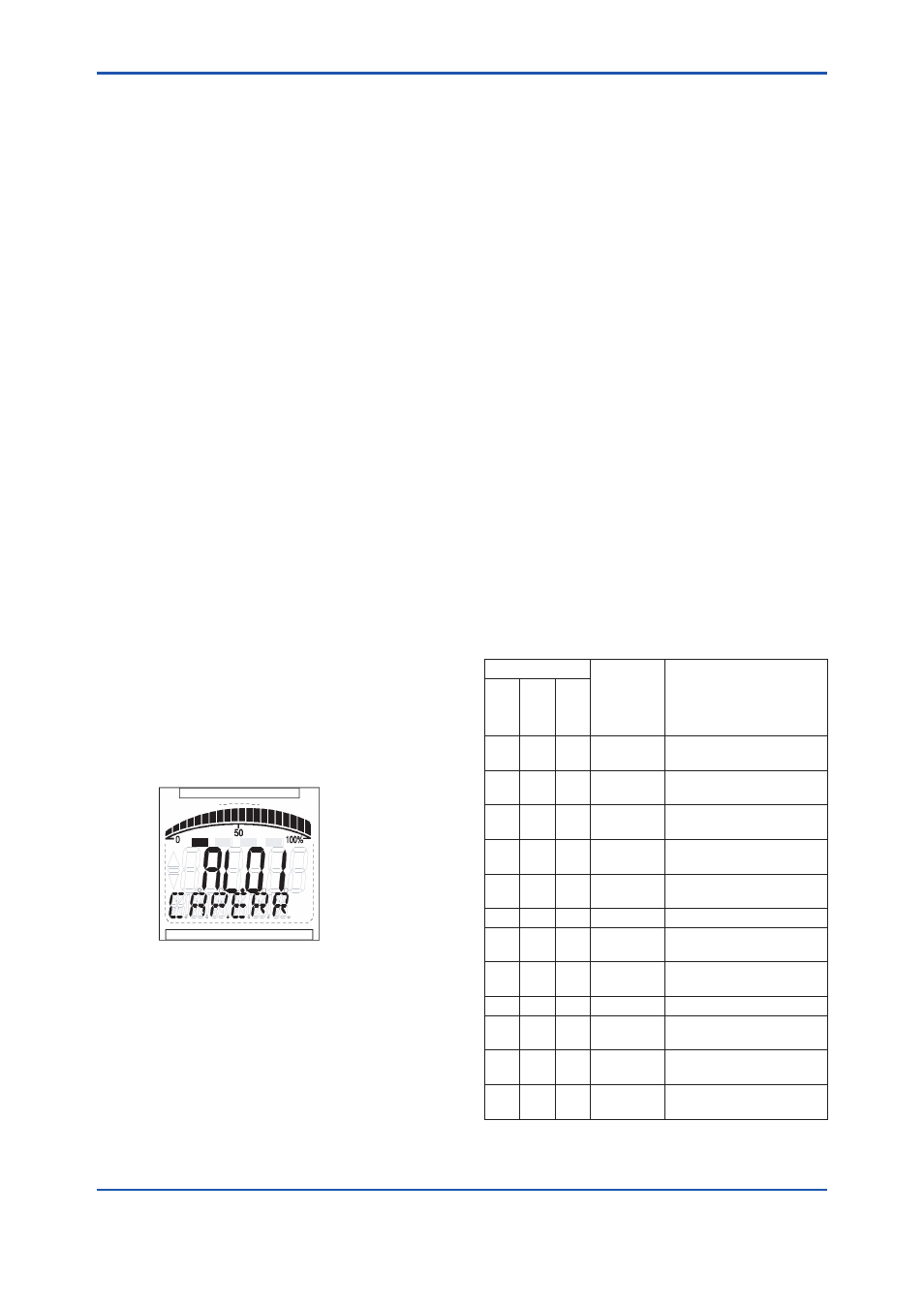
alarm is issued from each block. If an LCD indicator
is installed, the error number is displayed as AL.XX.
If two or more alarms are issued, multiple error
numbers are displayed.
For details of ALARM, refer to Section 8.2
F0701.ai
Figure 7.1
Error Identification on Indicator
7.2.2 Alarms and Events
The following alarms or events can be reported by
the EJX multivariable transmitter if Link object and
VCR static entry are set.
Analog Alerts (Generated when a process value
exceeds threshold)
By AI Block Hi-Hi Alarm, Hi Alarm, Low Alarm,
Low-Low Alarm
Discret Alerts (Generated when an abnormal
condition is detected)
By Resource Block Block Alarm, Write Alarm
By Transducer Block Block Alarm,
Diagnostic Alarm(option code: /DG1)
By AI, SC, IT, IS, AR and PID Blocks
Block Alarm
Update Alerts (Generated when an important
(restorable) parameter is updated)
By Resource Block Update Event
By Transducer Block Update Event
By AI, SC, IT, IS, AR and PID Blocks
Update Event
An alert has following structure:
Table 7.1
Alert Object
Subindex
Parameter
Name
Explanation
A
na
lo
g
A
le
rt
D
is
cr
et
e
A
le
rt
U
pd
at
e
A
le
rt
1
1
1 Block
Index
Index of block from which
alert is generated
2
2
2 Alert Key
Alert Key copied from the
block
3
3
3 Standard
Type
Type of the alert
4
4
4 Mfr Type
Alert Name identified by
manufacturer specific DD
5
5
5 Message
Type
Reason of alert
notification
6
6
6 Priority
Priority of the alarm
7
7
7 Time
Stamp
Time when this alert is
first detected
8
8
Subcode
Enumerated cause of this
alert
9
9
Value
Value of referenced data
10
10
Relative
Index
Relative index of
referenced data
8 Static
Revision
Value of static revision
(ST_REV) of the block
11
11
9 Unit Index Unit code of referenced
data