Warning – Yokogawa EJX930A User Manual
Page 18
<2. Handling Cautions>
2-7
IM 01C25R03-01E
WARNING
• In the case where the enclosure of the
Pressure Transmitter is made of aluminium,
if it is mounted in an area where the use of
category 1G apparatus is required, it must be
installed such, that even in the event of rare
incidents, ignition sources due to impact and
friction sparks are excluded.
• Electrostatic charge may cause an explosion
hazard. Avoid any actions that cause the
generation of electrostatic charge, such as
rubbing with a dry cloth on coating face of
the product.
• In the case where the enclosure of the
Pressure Transmitter is made of aluminum,
if it is mounted in an area where the use of
category 2D apparatus is required, it shall
be installed in such a way that the risk from
electrostatic discharges and propagating
brush discharges caused by rapid flow of
dust is avoided.
• To satisfy IP66 or IP67, apply waterproof
glands to the electrical connection port.
• When the lightning protector option is
specified, the apparatus is not capable
of withstanding the 500V insulation test
required by EN60079-11.
This must be taken into account when
installing the apparatus.
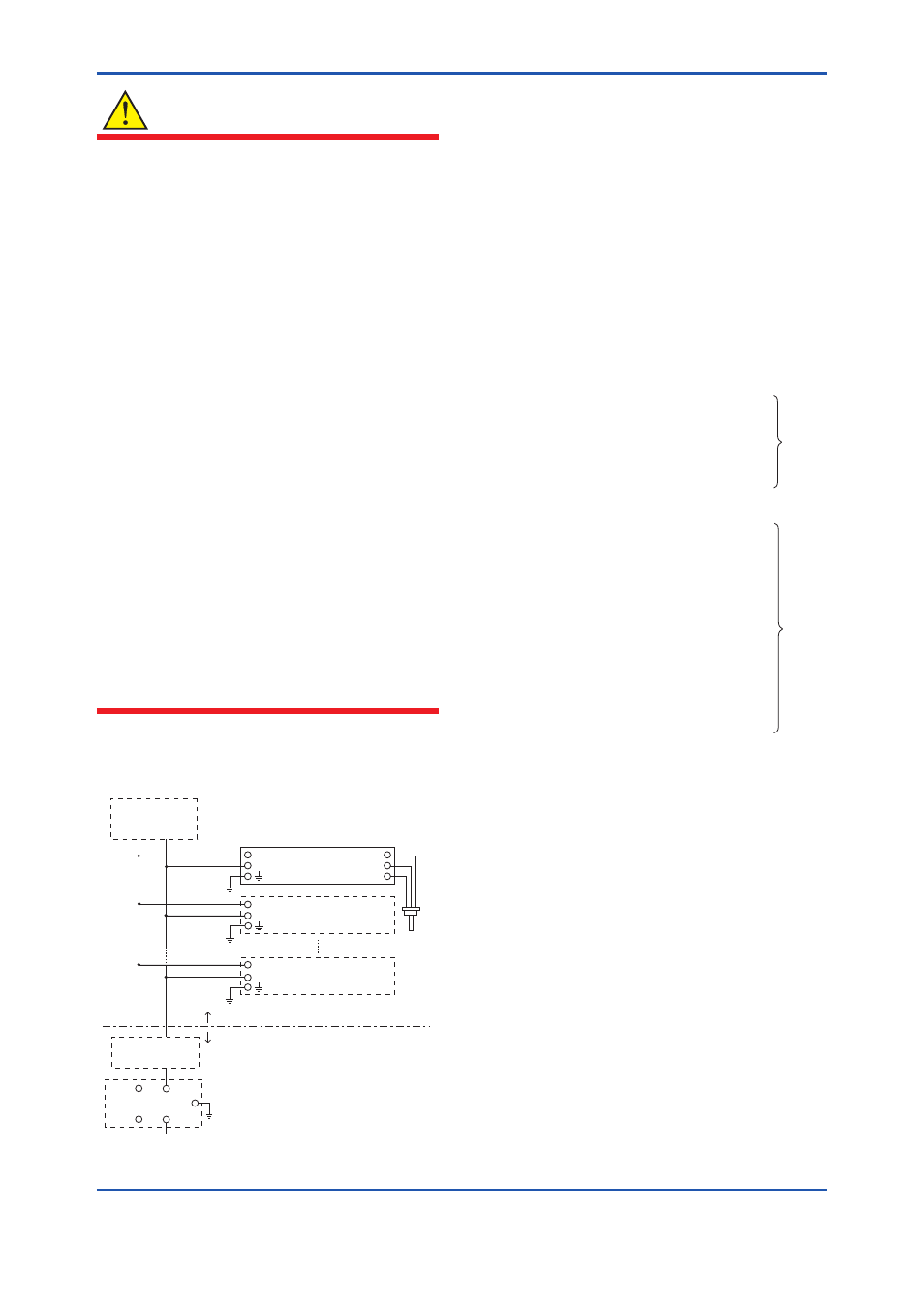
Note 6. Installation instructions
Non-Hazardous Location
Hazardous Location
F0308.ai
Terminator
Safety Barrier
Transmitter
Pressure
Transmitter
Transmitter
+
−
+
−
+
−
Terminator
+
−
+
−
[Installation Diagram]
SUPPLY
RTD
Pt100.3wire
• In the rating 1(*1), the output current of the
barrier must be limited by a resistor ‘Ra’ such
that Io = Uo/Ra.
• In the rating 2(*2), the output of the barrier
must be the characteristics of the trapezoid
or the rectangle and this transmitter can be
connected to Fieldbus equipment which are
in according to the FISCO model.
• The terminators may be built in by a barrier.
• More than one transmitter may be connected
to the power supply line.
• The terminator and the safety barrier shall be
certified.
Electrical data:
Supply circuit
Maximum Input Voltage Ui: 24 V
*1:
Rating 1
Maximum Input Current Ii: 250 mA
Maximum Input Power Pi: 1.2 W
Maximum Internal Capacitance Ci: 3.52 nF
Maximum Internal Inductance Li: 0 μH
or
Maximum Input Voltage Ui: 17.5 V
*2:
Rating 2
Maximum Input Current Ii: 380 mA
Maximum Input Power Pi: 5.32 W
Maximum Internal Capacitance Ci: 3.52 nF
Maximum Internal Inductance Li: 0 μH
or
Maximum Input Voltage Ui: 17.5 V
Maximum Input Current Ii: 460 mA
Maximum Input Power Pi: 5.32 W
Maximum Internal Capacitance Ci: 3.52 nF
Maximum Internal Inductance Li: 0 μH
Sensor circuit
Maximum Output Voltage Uo: 7.63 V
Maximum Output Current Io: 3.85 mA
Maximum Output Power Po: 0.008 W
Maximum Internal Capacitance Co: 4.8 μF
Maximum Internal Inductance Lo: 100 mH
• RTD sensor is prepared by the user.
The sensor signal line must suited a test
voltage of 500Vac.