Yokogawa EJX930A User Manual
Page 13
<2. Handling Cautions>
2-2
IM 01C25R03-01E
b. FM Intrinsically safe and Nonincendive
Type
EJX multivariable transmitter with optional code
/FS15.
• Applicable standard: FM3600, FM3610,
FM3611, FM3810, ANSI/NEMA250,
IEC60079-27
• FM Intrinsically Safe Approval
[Entity Model]
Class I, II & III, Division 1, Groups A, B, C,
D, F & G, Temperature Class T4 Ta=60ºC,
Type 4X and Class I, Zone 0, AEx ia IIC,
Temperature Class T4 Ta=60ºC, Type 4X
[FISCO Model]
Class I, II & III, Division 1, Groups A, B, C,
D, F & G, Temperature Class T4 Ta=60ºC,
Type 4X and Class I, Zone 0, AEx ia IIC,
Temperature Class T4 Ta=60ºC, Type 4X
• Nonincendive Approval
Class I, Division 2, Groups A, B, C & D
Temperature Class T4 Ta=60ºC, Type 4X
and Class II, Division 2, Groups F & G
Temperature Class T4 Ta=60ºC, Type 4X
and Class I, Zone 2, Group IIC, Temperature
Class T4 Ta=60ºC, Type 4X and Class III,
Division 1, Temperature Class T4 Ta=60ºC,
Type 4X
• Electrical Connection: 1/2 NPT female, M20
female
• Caution for FM Intrinsically safe type.
(Following contents refer to “DOC. No.
IFM026-A12 p.1 to p.4.”)
■ IFM026-A12
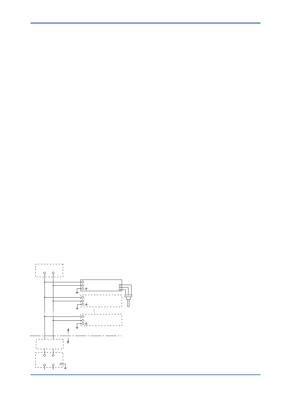
● Installation Diagram for Intrinsically safe
(Division 1 Installation)
Non-Hazardous Location
Hazardous Location
F0201.ai
Terminator
Safety Barrier
Field Instruments
Pressure
Transmitter
Field Instruments
+
–
+
–
+
–
Terminator
+
–
+
–
Note 1. Barrier must be installed in an enclosure
that meets the requirements of ANSI/ISA
61010-1.
Note 2. Control equipment connected to the Associ
ated Apparatus must not use or generate
more than 250 Vrms or Vdc.
Note 3. Installation should be in accordance
with ANSI/ISA 12.06.01 “Installation of
Intrinsi cally Safe Systems for Hazardous
(Classified) Locations” and the National
Electrical Code (ANSI/NFPA 70) Sections
504 and 505.
Note 4. The configuration of Associated Apparatus
must be Factory Mutual Research
Approved under FISCO Concept.
Note 5. Associated Apparatus manufacturer’s
installa tion drawing must be followed
when installing this equipment.
Note 6. No revision to drawing without prior
Factory Mutual Research Approval.
Note 7. Terminator must be FM Approved.
Note 8. Note a warning label worded “SUBSTITU
TION OF COMPONENTS MAY IMPAIR
INTRINSIC SAFETY”, and “INSTALL IN
ACCORDANCE DOC.NO.IFM026-A12 P.1
TO 4.”
Electrical Data:
• Rating 1 (Entity)
For Groups A, B, C, D, F, and G or Group IIC
Maximum Input Voltage Vmax: 24 V
Maximum Input Current Imax: 250 mA
Maximum Input Power Pmax: 1.2 W
Maximum Internal Capacitance Ci: 3.52 nF
Maximum Internal Inductance Li: 0 mH
or
• Rating 2 (FISCO)
For Groups A, B, C, D, F, and G or Group IIC
Maximum Input Voltage Vmax: 17.5 V
Maximum Input Current Imax: 380 mA
Maximum Input Power Pmax: 5.32 W
Maximum Internal Capacitance Ci: 3.52 nF
Maximum Internal Inductance Li: 0 mH
or
• Rating 3 (FISCO)
For Groups C, D, F, and G or Group IIB
Maximum Input Voltage Vmax: 17.5 V
Maximum Input Current Imax: 460 mA
Maximum Input Power Pmax: 5.32 W
Maximum Internal Capacitance Ci: 3.52 nF
Maximum Internal Inductance Li: 0 mH