4 setting of tags and addresses, Setting of tags and addresses -3 – Yokogawa EJX930A User Manual
Page 30
<5. Configuration>
5-3
IM 01C25R03-01E
Table 5.3
Execution Schedule of the EJX
Function Blocks
Index
Parameters
Setting (Enclosed is
factory-setting)
269
(SM)
MACROCYCLE_
DURATION
Cycle (MACROCYCLE)
period of control or
measurement. Unit is 1/32
ms. (16000 = 0.5 s)
276
(SM)
FB_START_
ENTRY.1
AI1 block startup time.
Elapsed time from the start of
MACROCYCLE specified in
1/32 ms. (0 = 0 s)
277
(SM)
FB_START_
ENTRY.2
AI2 block startup time.
Elapsed time from the start of
MACROCYCLE specified in
1/32 ms. (8000 = 250 ms)
278
(SM)
FB_START_
ENTRY.3
AI3 block startup time.
Elapsed time from the start of
MACROCYCLE specified in
1/32 ms. (16000 = 500 ms)
279
(SM)
FB_START_
ENTRY.4
AI4 block startup time.
Elapsed time from the start of
MACROCYCLE specified in
1/32 ms. (24000 = 750 ms)
280
to
289
(SM)
FB_START_
ENTRY.5
to
FB_START_
ENTRY.14
Not used.
A maximum of 30 ms is taken for execution of
AI block. For scheduling of communications for
combination with the next function block, the
execution is so arranged as to start after a lapse
of longer than 30 ms. In no case should function
blocks of the EJX be executed at the same time
(execution time is overlapped).
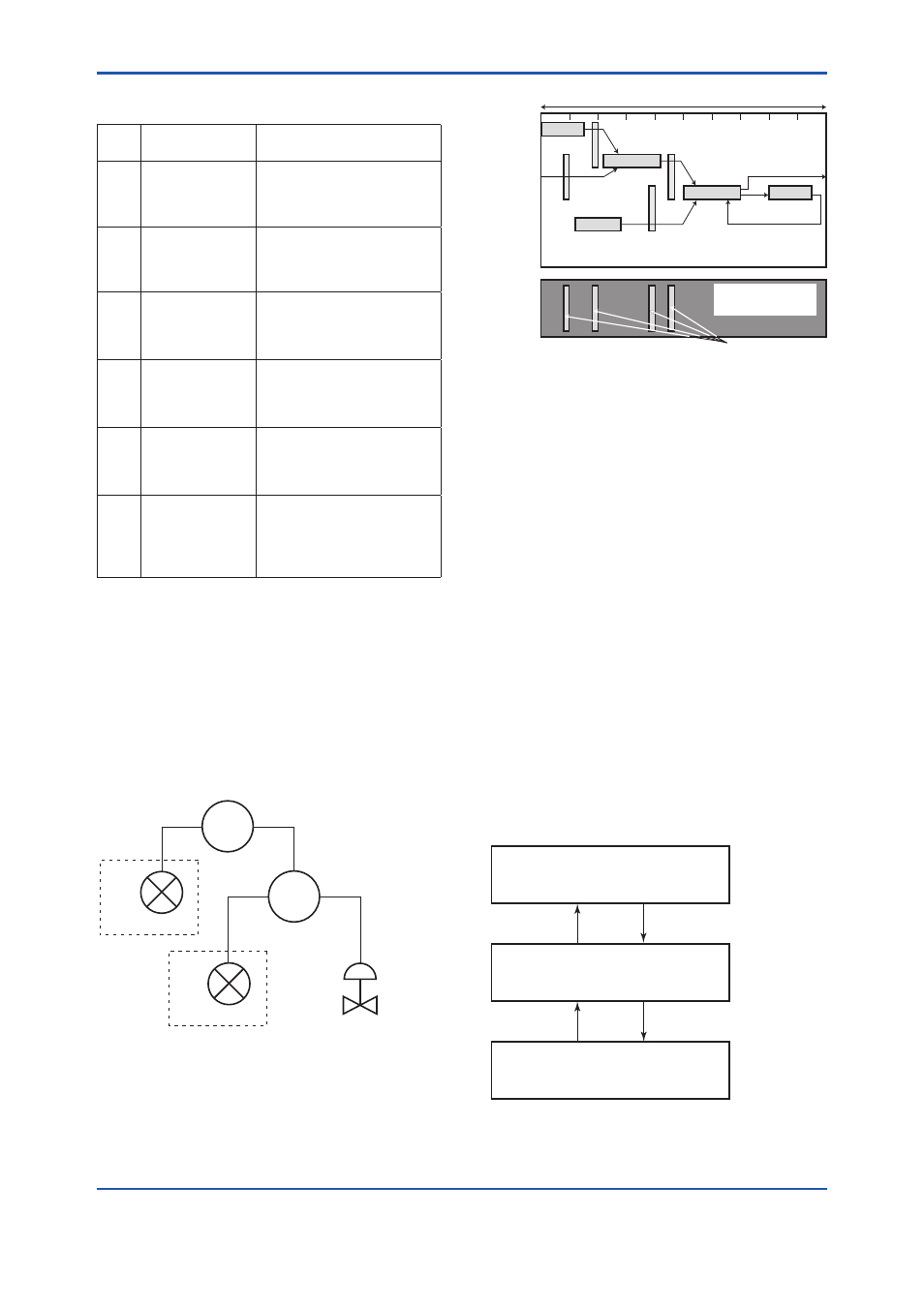
Figure 5.3 shows an example of schedule based on
the loop shown in Figure 5.2.
F0502.ai
LIC100
FIC100
FC100
FI100
EJX
#2
LI100
EJX
#1
Figure 5.2
Example of Loop Connecting
Function Block of Two EJX with Other
Instruments
LI100
LIC100
FIC100
FC100
FI100
Commu-
nication
Schedule
OUT
IN
OUT
CAS_IN
BKCAL_OUT
BKCAL_IN
BKCAL_IN
BKCAL_OUT
IN
Unscheduled
Communication
Scheduled
Communication
F0503.ai
Macrocycle (Control Period)
Figure 5.3
Function Block Schedule and
Communication Schedule
When the control period (macrocycle) is set to more
than 4 seconds, set the following intervals to be
more than 1% of the control period.
- Interval between “end of block execution” and
“start of sending CD from LAS”
- Interval between “end of block execution” and
“start of the next block execution”
5.4 Setting of Tags and
Addresses
This section describes the steps in the procedure
to set PD Tags and node addresses in the EJX
multivariable transmitter. There are three states of
Fieldbus devices as shown in Figure 5.4, and if the
state is other than the lowest SM_OPERATIONAL
state, no function block is executed. EJX must be
transferred to this state when an EJX tag or address
is changed.
UNINITIALIZED
(No tag nor address is set)
Tag clear
Tag setting
INITIALIZED
(Only tag is set)
SM_OPERATIONAL
(Tag and address are retained, and
the function block can be executed.)
Address clear
F0504.ai
Address setting
Figure 5.4
Status Transition by Setting PD Tag and
Node Address