3 atex certification, Atex certification -6 – Yokogawa EJX930A User Manual
Page 17
<2. Handling Cautions>
2-6
IM 01C25R03-01E
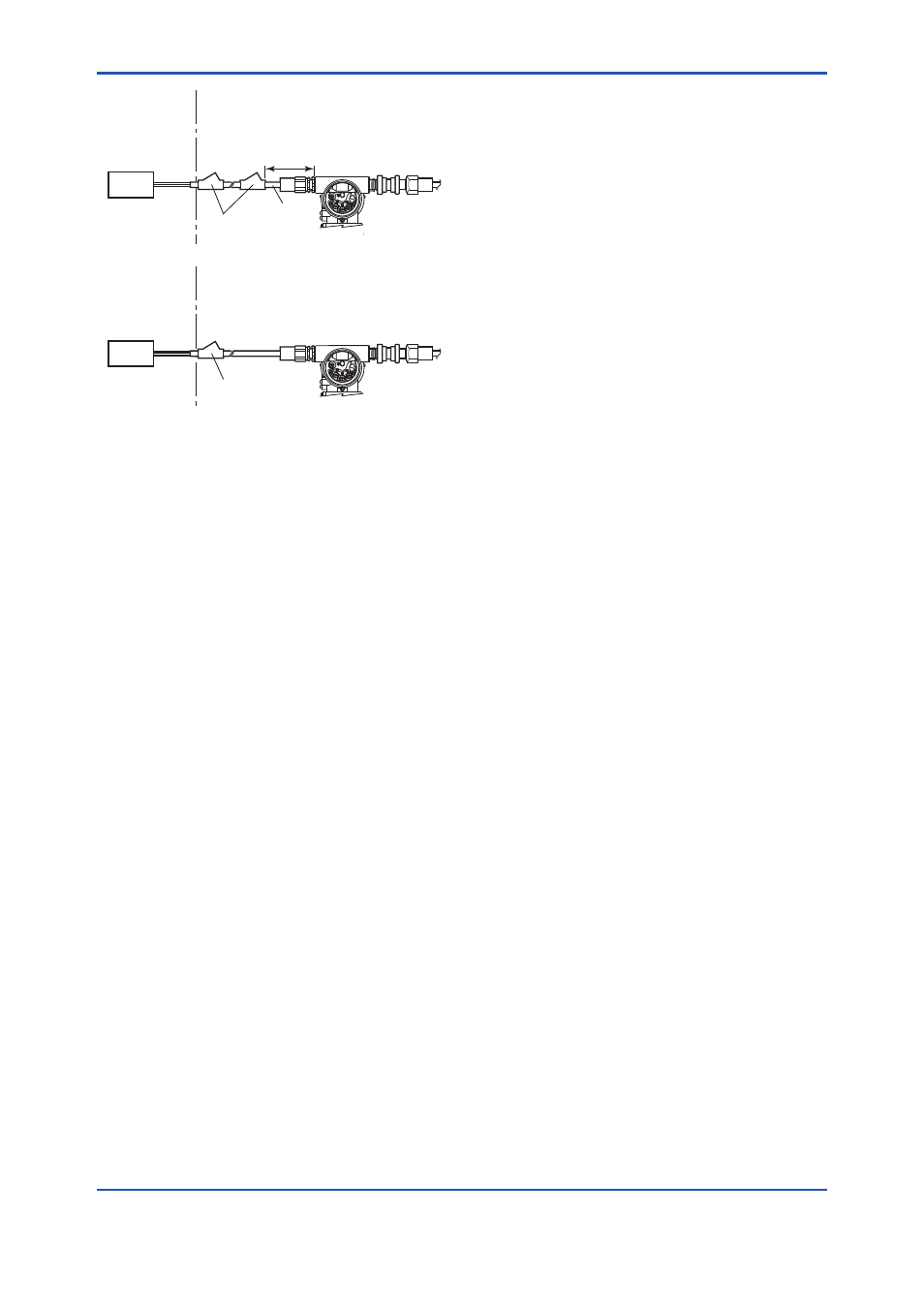
Non-hazardous
Location
Equipment
32 V DC Max.
15 mA DC
Signal
Non-Hazardous
Locations
Hazardous Locations Division 1
Non-Hazardous
Locations
Hazardous Locations Division 2
50 cm Max.
Sealing Fitting
Conduit
Non-hazardous
Location
Equipment
32 V DC Max.
15 mA DC
Signal
Sealing Fitting
F0204.ai
SUPPLY
PUL
SE
CHECK
ALARM
SUPPLY
PUL
SE
CHECK
ALARM
SUPPLY
PULSE
CHECK
ALARM
SUPPL
Y
PULSE
CHECK
ALARM
Multivariable Transmitter
Multivariable Transmitter
2.1.3 ATEX Certification
(1) Technical Data
a. ATEX Intrinsically Safe Type
Caution for ATEX Intrinsically safe type.
Note 1. EJX multivariable transmitter with optional
code /KS26 for potentially explosive
atmospheres:
• No. KEMA 06ATEX0278 X
• Applicable Standard: EN 60079-0:2009,
EN 60079-11:2012, EN 60079-26:2007
Note 2. Ratings
Type of Protection and Marking Code:
Ex ia IIC/IIB T4 Ga
Ex ia IIIC T85°C T100°C T120°C Db
Group: II
Category: 1G, 2D
Ambient Temperature for EPL Ga:
–40 to 60°C
Ambient Temperature for EPL Db:
–30* to 60°C
* –15°C when /HE is specified.
Maximum Process Temperature (Tp.): 120°C
Maximum Surface Temperature for EPL Db.
T85°C (Tp.: 80°C)
T100°C (Tp.: 100°C)
T120°C (Tp.: 120°C)
Ambient Humidity:
0 to 100% (No condensation)
Degree of Protection of the Enclosure:
IP66/IP67
Electrical Data
• When combined with Trapezoidal or
Rectanglar output characteristic FISCO
model IIC barrier
[Supply circuit (terminals + and -)]
Ui = 17.5 V, Ii = 380 mA, Pi = 5.32 W,
Ci = 3.52 nF, Li = 0 µH
[Sensor circuit]
Uo = 7.63 V, Io = 3.85 mA, Po = 0.008 W,
Co = 4.8 µF, Lo = 100 mH
• When combined with Linear characteristic
barrier
[Supply circuit (terminals + and -)]
Ui = 24 V, Ii = 250 mA, Pi = 1.2 W,
Ci = 3.52 nF, Li = 0 µH
[Sensor circuit]
Uo = 7.63 V, Io = 3.85 mA, Po = 0.008 W,
Co = 4.8 µF, Lo = 100 mH
• When combined with Trapezoidal or
Rectanglar output characteristic FISCO
model IIB barrier
[Supply circuit (terminals + and -)]
Ui = 17.5 V, Ii = 460 mA, Pi = 5.32 W,
Ci = 3.52 nF, Li = 0 µH
[Sensor circuit]
Uo = 7.63 V, Io = 3.85 mA, Po = 0.008 W,
Co = 4.8 µF, Lo = 100 mH
Note 3. Installation
• All wiring shall comply with local installation
requirements. (Refer to the installation
diagram)
Note 4. Maintenance and Repair
• The instrument modification or parts
replacement by other than authorized
representative of Yokogawa Electric
Corporation is prohibited and will void
DEKRA Intrinsically safe Certification.
Note 5. Special Conditions for Safe Use